SECTION 58 - ATTACHMENTS / HEADERS - CHAPTER 2
58-14
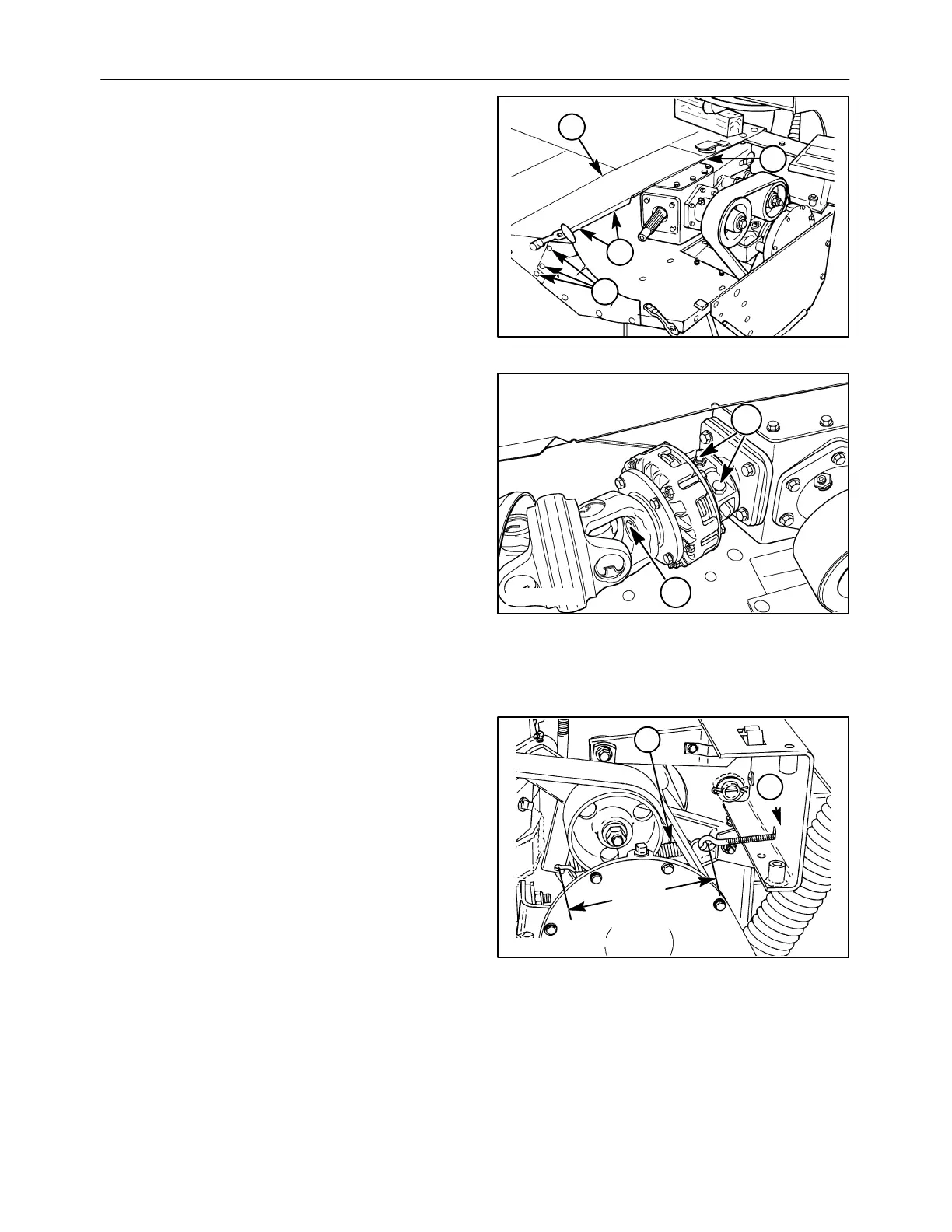
3. Reinstall the shielding, 1, by sliding the edge
between the lower shield and header frame until
the bolt holes line up. Retain the shield using four
5/16″ x1″ carriage bolts, flat washers and flange
nuts at 2 and four 3/8″ x1″ carriage bolts, flat
washers and flange nuts at 3.
1411/6-13
1
2
3
3
28
4. Slide the slip clutch onto the bevel drive gearbox
input shaft as far as possible. Install the cap
screw, 1, and lock washer into the slip clutch
yoke, and thread it into the end of the shaft.
Tighten the cap screw as much as possible to pull
the slip clutch hub securely onto the tapered end
of the gearbox shaft. Reinstall the two cap
screws, 2, and locknuts at the rear of the slip
clutch assembly; torque to 87 N⋅m (64 ft-lb).
NOTE: Do not overtorque; the locknuts are Class C,
and are limited to 87 N
⋅
m (64 ft-lb).
IMPORTANT: The slip clutch end of the secondary
PTO shaft is very heavy and awkward; use caution
not to drop the shaft assembly as personal injury or
damage to the CV joint may result.
50012123
1
2
29
5. Block the cutter bar to lock up the driveline, and
torque the conditioner drive sheave retaining bolt
to 397 N⋅m (293 ft-lb). Install the conditioner drive
belt over the idler and onto the drive sheave.
Connect the tension spring, 1, to the idler arm,
and tighten the nuts, 2, on the spring tension rod
until the spring measures 279 mm (11 in)
between the spring hooks.
1
2
279 mm
(11 in)
A3994-09
30