SECTION 58 - ATTACHMENTS / HEADERS - CHAPTER 1
58-5
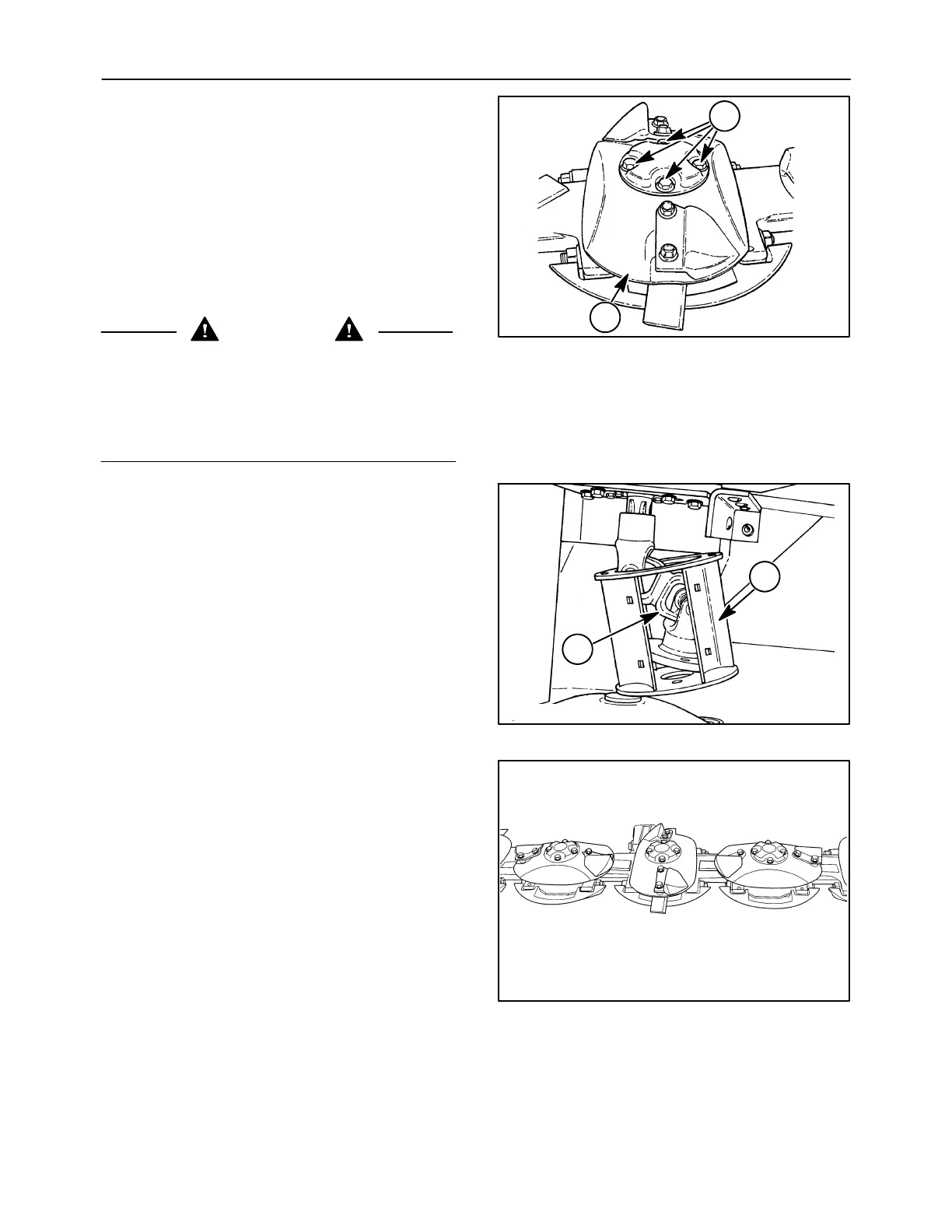
DISCS
Each time knives are replaced or turned, check the
discs for damage and wear. If a disc is bent or
cracked, replace it. When the leading edge, 1, of the
disc wears thin, it can be used on an opposite rotating
module to utilize the second face.
IMPORTANT: Do not make weld repairs to the discs,
as this will affect disc strength and balance.
Remove discs by removing four bolts at 2.
WARNING
Disengage the PTO, turn off the tractor engine
and remove the key. Wait for all movement to
stop before leaving operator’s position. Never
adjust, lubricate, clean or unplug machine with
the engine running. Failure to comply could
result in death or serious injury.
2--48
1
2
9
Discs with towers can also be removed. On the right
side, remove the four retaining bolts, and remove the
tower and disc.
On the left side, it will be necessary to remove the
wear plates, if equipped, from the tower, 1, to provide
additional clearance. Remove the four retaining
bolts, and slide the tower, 1, and drive shaft, 2,
upwards and to the side in order to remove the disc.
50011833
1
2
10
Reinstall discs at right angles to each other as
shown. Position the end towers so that the notches
in tower base align with the slots in the disc. Be sure
the correct hardware is installed as follows:
Discs w/caps: 1/2″ x1″ cap screws.......
cupped lock washers
Right end disc
& tower: 1/2″ x1-1/4″ cap screws...........
thick hardened washers
Left end disc, tower
& drive shaft: 1/2″ x1-3/4″ cap screws.......
thick hardened washers
IMPORTANT: Use of incorrect disc retaining
hardware may cause cutter bar lock-up and potential
damage, or may prevent proper retention of discs.
Torque retaining bolts to 113 N⋅m (83 ft-lb).
NOTE: Do not overtighten as bolts may yield.
19981908
11