SECTION 58 - ATTACHMENTS / HEADERS - CHAPTER 3
58-32
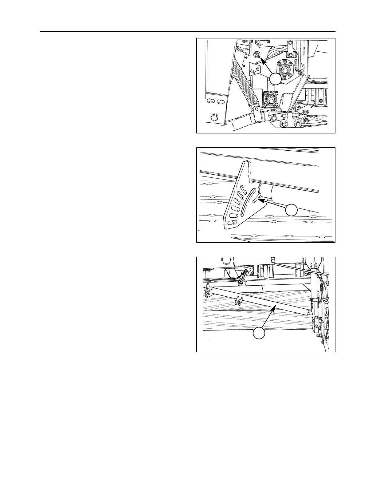
5. Remove the cotter pin and washers at each end
of the swathgate where it fits through the header
frame, 1. Slide the swathgate to the right so that
the swathgate handle disengages from the
adjusting quadrant and the left end slips out of
the header frame. Lower the left end so that the
swathgate slide to the left to remove the right end
from the header. Set the swathgate aside.
A5049-3
1
85
6. Remove the groove pin, 1, at the inner end of the
adjusting tube by driving it out of the tube.
50012164
1
86
7. Slide the adjusting tube, 1, inwards until the outer
end comes off the right side tension arm hub. If
the torsion bar does not fully slide out of the right
side tension arm, loosen the retaining cap screw
on the right side pivot arm, and pivot the plate
downwards. Use a hammer and punch to drive
the torsion bar inwards out of the tension arm. Tip
the outer ends of the adjusting tube and torsion
bar assembly, 1, down and to the rear of the
machine until it can be slid outwards and out of
the inside mount on the header frame.
8. Slide the torsion bar out of the adjusting tube.
50012166
1
87