SECTION 58 - ATTACHMENTS / HEADERS - CHAPTER 3
58-12
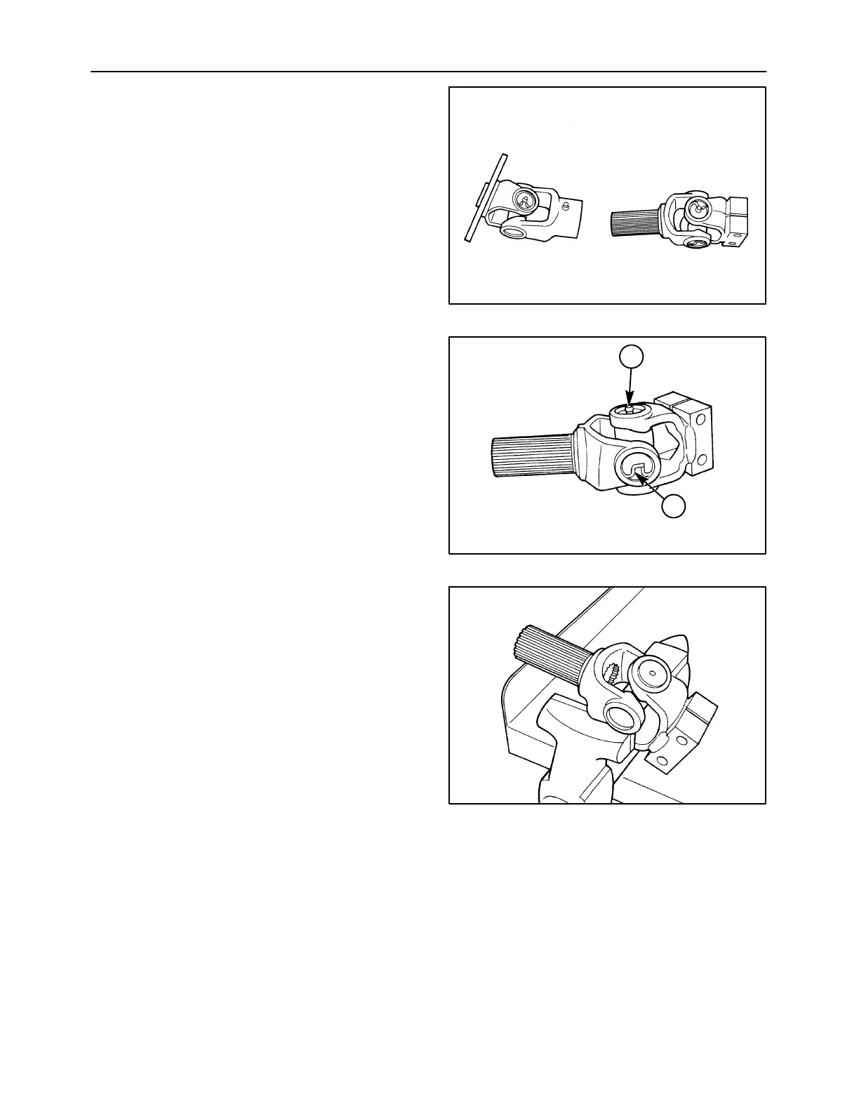
2. The drive shaft can be slid apart, and each end
serviced separately.
1411/8-5
27
3. Remove the internal snap rings, 1, from the
U-joint using pliers. Remove the grease zerk, 2,
from one bearing cup before the snap ring may
be removed.
NOTE: The grease zerk, 2, is oriented to line up with
other grease zerks on the driveline. Note the
positioning of the grease zerk prior to removal.
1411/8-6
1
2
28
4. Position the joint in an open vise, with each ear
of one yoke supported by a vise jaw.
5. With a soft hammer or mallet, strike the top ear
of the unsupported yoke. This will drive the top
bearing outward approx. 8 mm (1/4″).
IMPORTANT: Do not use a hard faced hammer, as
this may damage the edge of the bearing cup bore in
the yoke or the snap ring groove area, causing the
bearing cup to hang-up or seize in the yoke.
6. Pull the bearing out of the yoke ear. If necessary,
grip the loosened bearing in a vise, and drive the
yoke off the bearing by striking yoke ear with the
soft-faced hammer or mallet.
7. This same procedure should be followed to
remove the bearing directly opposite the one just
removed, after which the yoke itself may be
removed.
1411/8-7
29