SECTION 31 - IMPLEMENT POWER TAKE-OFF (PTO) - CHAPTER 1
31-19
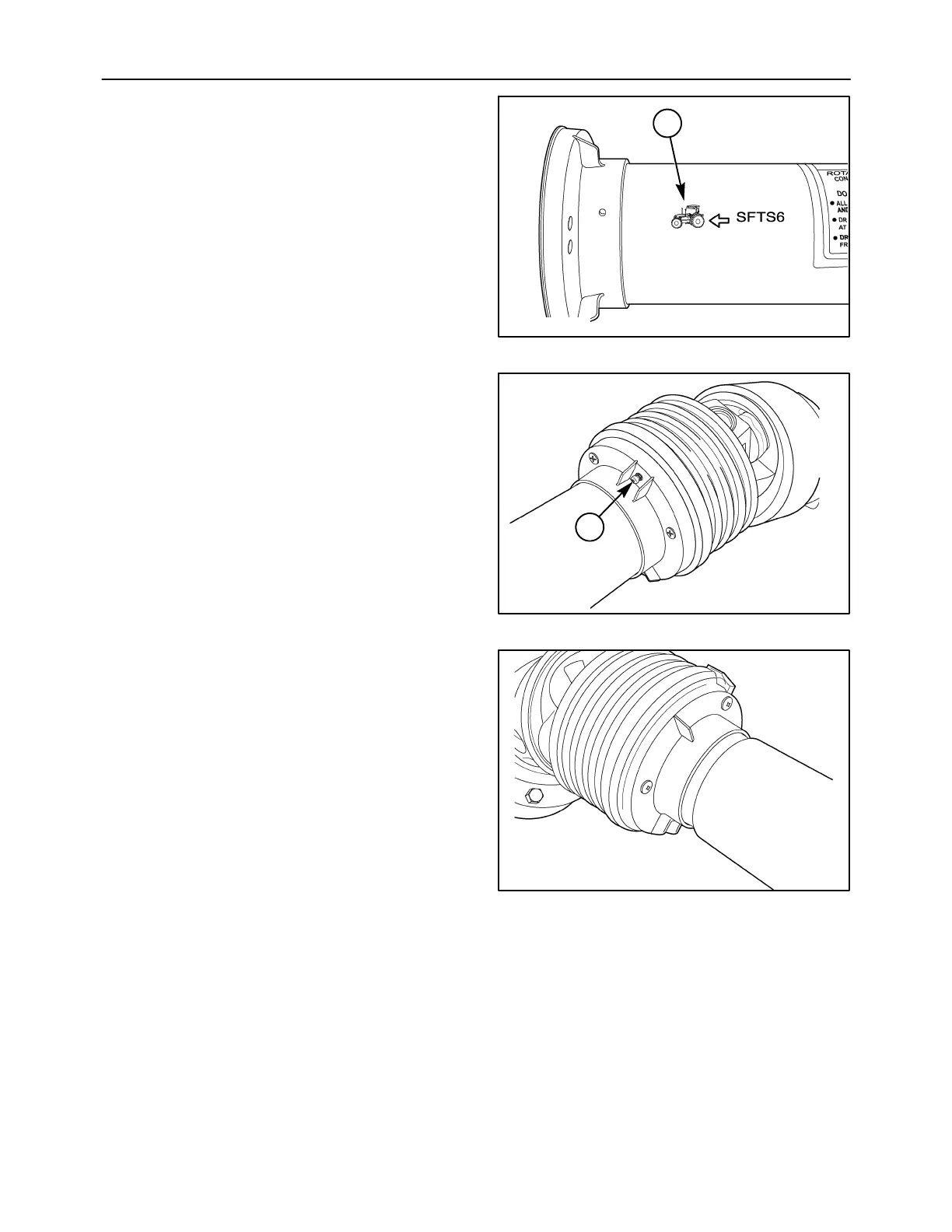
5. Slide the two guards together.
6. Place the guards onto the female PTO shaft.
NOTE: The end with the tractor image, 1, goes
opposite the end with the clutch.
86065254
1
48
7. Align the grease fitting, 1, with the square notch
cut into the guard. Secure the cone guard and
guard to the support ring with screws.
86065262
1
49
8. Now, slide the two shafts together.
9. Align the grease fitting with the square notch cut
into the guard. Secure the cone guard and guard
to the support ring with screws.
86065255
50