190 • SMP Gateway User Manual
19.3.6 Monitoring Redundancy Status
The GRP LED on the front panel of the SMP 16 displays the redundancy status, as does the ST2
LED on the front panel of the SMP 4-20 and SMP 8-40.
Refer to your SMP Gateway installation guide for details.
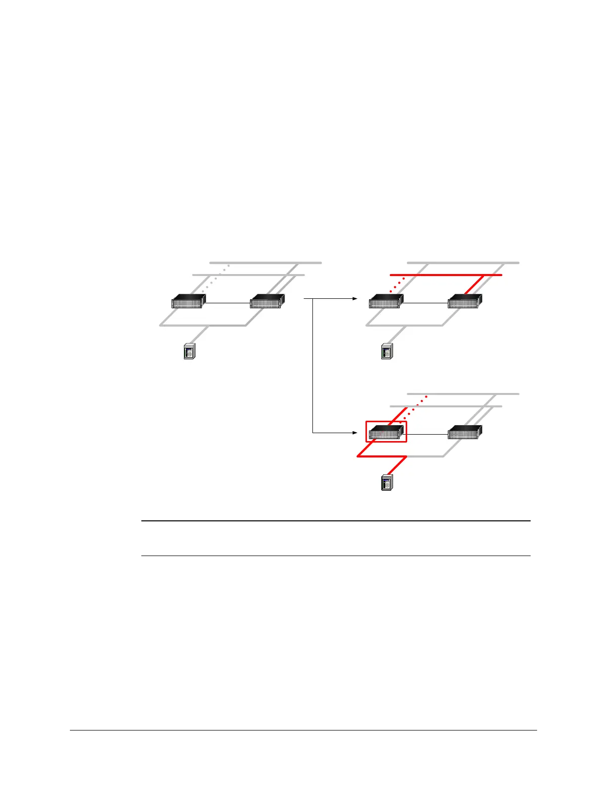
19.3.7 Testing a Redundant Network
So far, we have discussed SMP Gateway redundancy. However, with the SMP 16 and the SMP 8-
40, you can also set up network redundancy. The SMP Gateways and the control center can
communicate via either network. Next figure illustrates a typical redundant network configuration,
where the control center communicates with an SMP Gateway group through two subnetworks.
10.2.15.1 10.3.30.2
10.2.15.3
STANDBYACTIVE
10.3.30.1 10.2.15.2
10.3.30.3
10.2.15.1 10.3.30.2
10.2.15.3
STANDBYACTIVE
10.3.30.1 10.2.15.2
10.3.30.3
NETWORK
FAILURE
10.2.15.1 10.3.30.2
10.2.15.3
ACTIVE
10.3.30.1 10.2.15.2
10.3.30.3
SMP
FAILURE
Note: Setting up a redundant network is out of the scope of this document. However,
the following procedure describes how you can use the SMP Tools’ IP address
switching feature to test a redundant network configuration.
Normally, the control center accesses the primary network and switches to the secondary network
only if the primary network fails. You should therefore make sure the secondary network is
working properly. To do this, you need to switch to the secondary IP address of your
SMP Gateway, and then run SMP Log and SMP Trace.To switch from the first IP address to the
second IP address:
From SMP Manager’s Tools menu, click Use Second Address.
Note that the switch to the second IP address applies not only to the SMP Gateway that is in
the redundant network, but to all the gateways in the list. From this point on, if you launch