Tighten the cylinder head capscrews of the single cylin-
der compressor in an alternating sequence.
Torque Value: Step 1 6.8 N•m [5 ft-lb]
Step 2 14 N•m [10 ft-lb]
Step 3 20 N•m [15 ft-lb]
Step 4 27 N•m [20 ft-lb]
Install the intake valve spring with the tang down.
Install the intake valve.
Install the intake valve seat with the flange side up.
Install the unloader valve cap spring.
Install the unloader valve cap.
Use anti-seize compound to lubricate the outside diam-
eter of the cap.
NOTE: The rectangular ring seal must be installed with the
grooved side up.
Install the rectangular ring seal.
Install the o-ring seal.
Use clean engine oil to lubricate the o-ring seal.
Install the unloading valve body.
NOTE: Press the unloading valve body down to be sure the
tangs of the unloader valve cap are in the three slots of the
intake valve seat.
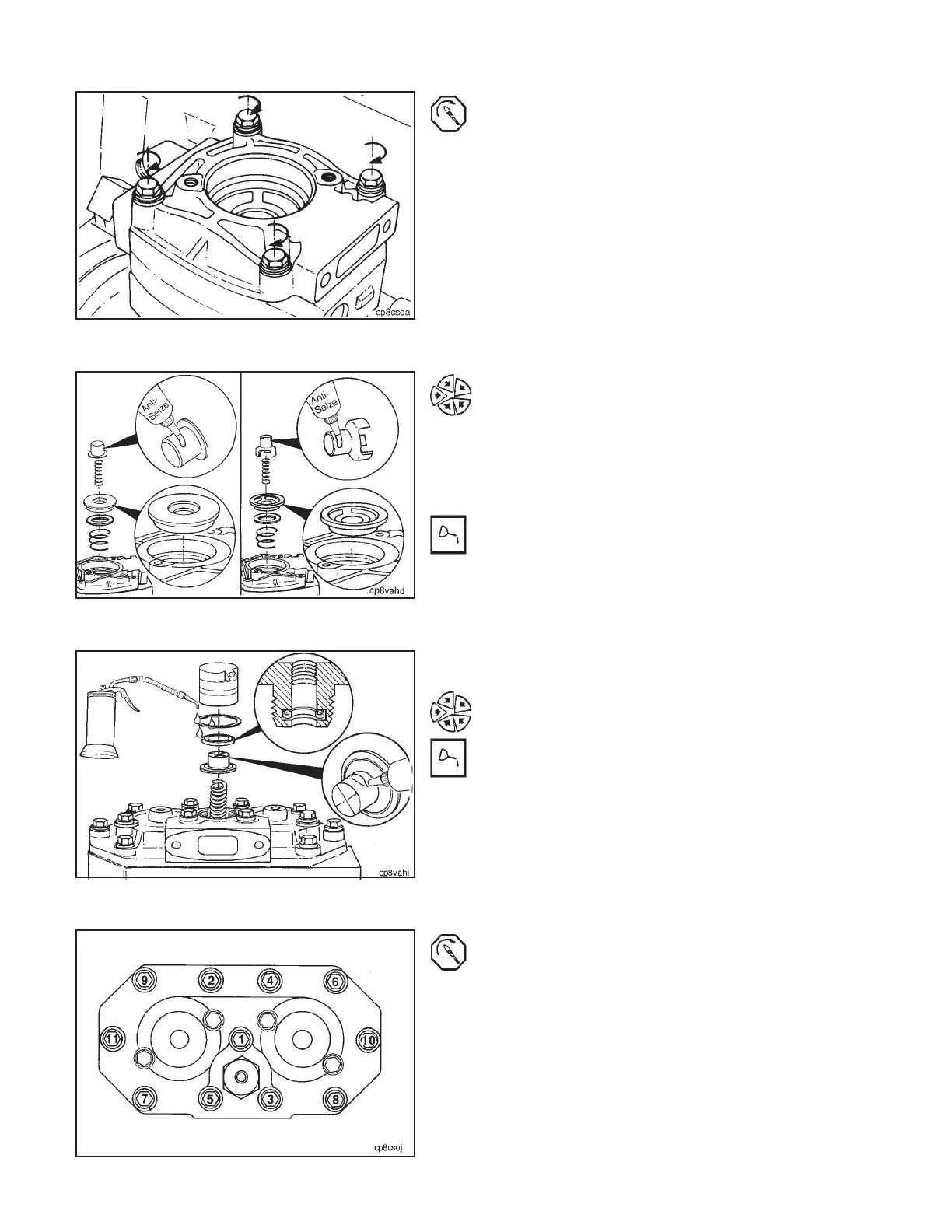
Tighten the cylinder head capscrews of the Holset or
Cummins two cylinder compressor in the sequence
shown.
NOTE: Be sure the center unloader valve assembly has
been installed before tightening the head capscrews.
Torque Value: Step 1 14 N•m [10 ft-lb]
Step 2 27 N•m [20 ft-lb]
Step 3 41 N•m [30 ft-lb]
Air Compressor, Cylinder Head (4-06) Section 4 - Compressed Air System
N14Page 4-20