Engine Dynamometer - Install Engine
(8-01)
NOTE: Be sure the dynamometer capacity is sufficient to
permit testing at 100 percent of the engine rated horse-
power. If the capacity is not enough, the testing procedure
must be modified to the restrictions of the dynamometer.
Use engine lifting fixture, Part No. 3822512, to install the
engine to the test stand. Align and connect the dyna-
mometer. Refer to the manufacturer’s instructions for
aligning and testing the engine.
Refer to Service Bulletin No. 3666005, Dynamometer and
Road Engine Testing, for detailed instructions on auxil-
iary aftercooling system attachment.
NOTE: Some engines are equipped with fittings used for
CompuchekT testing sensors. The sensor probes used for
CompuchekT and dynamometer testing are not compatible.
If the same location is used, remove the CompuchekT fitting
and install adapters for the dynamometer sensor.
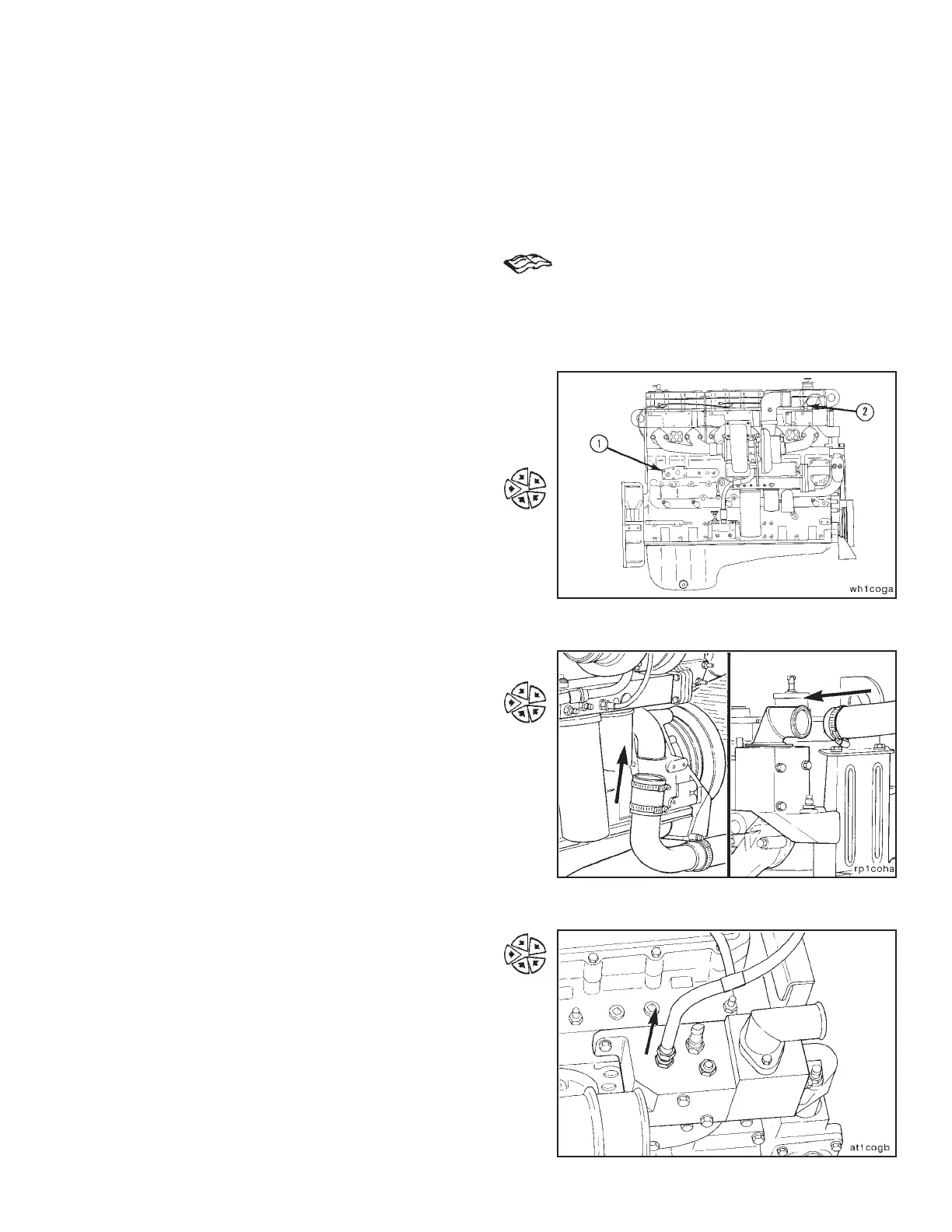
Install the coolant pressure sensor (1).
Install the coolant temperature sensor (2).
Coolant Plumbing
Connect the coolant supply to the water inlet connection.
Connect the coolant return to the water outlet connection.
Install the drain plugs and close all of the water drain
cocks.
Loosen the cooling system vent line.
Fill the system with coolant until it flows from the vent.
Tighten the vent line and finish filling the system.
Engine Testing Engine Dynamometer - Install Engine (8-01)
N14 Page 8-9