Non CELECT™ Engines:
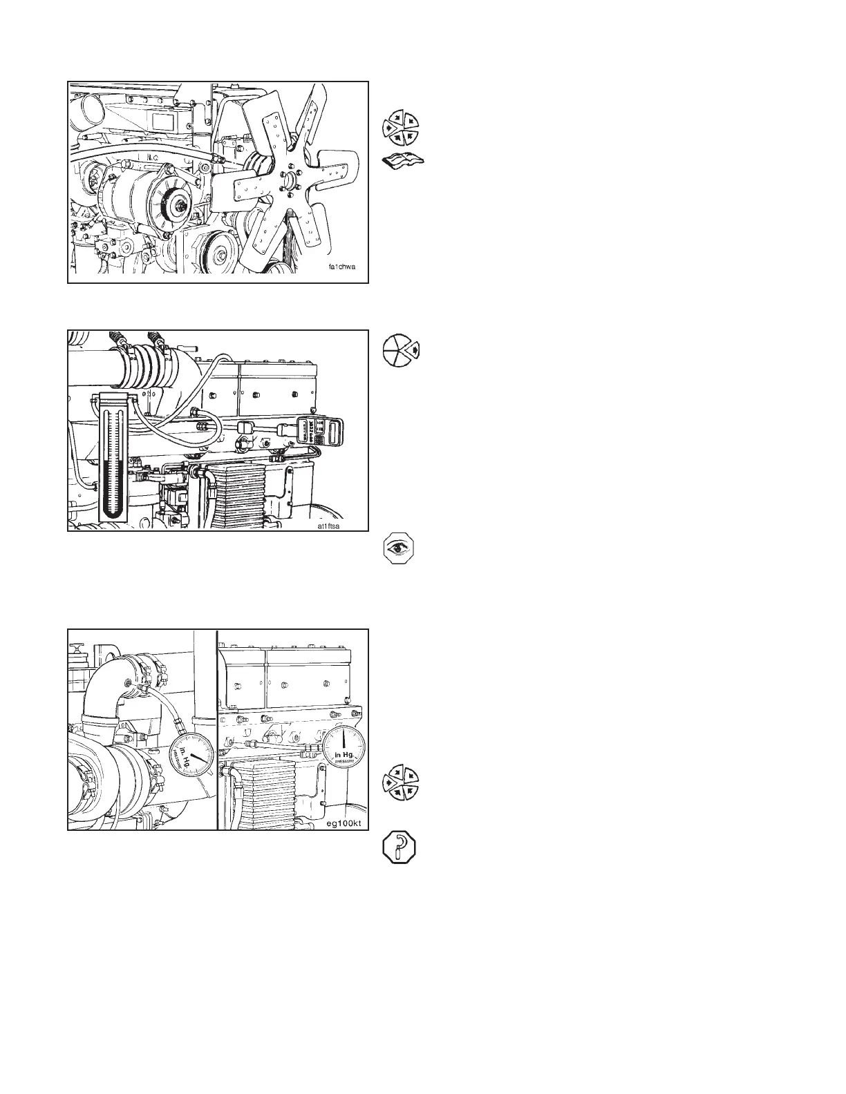
Lock the cooling fan in the ‘‘ON’’ mode. This can be done
by installing a jumper across the temperature switch, or
by supplying shop air to the control valve. Refer to the fan
drive manufacturer for the recommended procedure.
Remove any obstructions to the air flow across the CAC
such as a winterfront.
Manually lock the shutters in the ‘‘OPEN’’ position if
equipped.
Install a Fluke digital thermometer, Part No. 3822666,
and attach thermocouple wire kit, Part No. 3822988, into
the intake manifold.
Monitor the intake manifold temperature. The tempera-
ture must not exceed 77°C [170°F].
If the intake manifold temperature exceeds the above
limits, shutoff the engine. Allow the engine to cool.
Inspect the CAC fins for obstructions to the air flow.
Check the fan drive to make sure it is locked in the ‘‘ON’’
mode.
Resume the test.
Charge Air Cooler Restriction
Measure the intake pressure drop across the charge air
cooler.
This test can be done with a mercury manometer or two
separate gauges, Part No. ST-1273. If two gauges are
being used, calibrate both gauges on a common pressure
source at 206 kPa [30 PSI] to ensure consistency.
Install one pressure gauge, Part No. ST-1273, in the
fitting in the turbocharger compressor outlet elbow. In-
stall the other pressure gauge in the fitting in the intake
manifold.
Observe the reading on the gauges. Pressure drop must
not be greater than:
102 mm Hg [4.0 in. Hg]
14 kPa [2.0 psi]
General Test Procedure - Chassis Dynamometer (8-06) Engine Testing
N14Page 8-46