Combustion Air System Specifications - Section 3
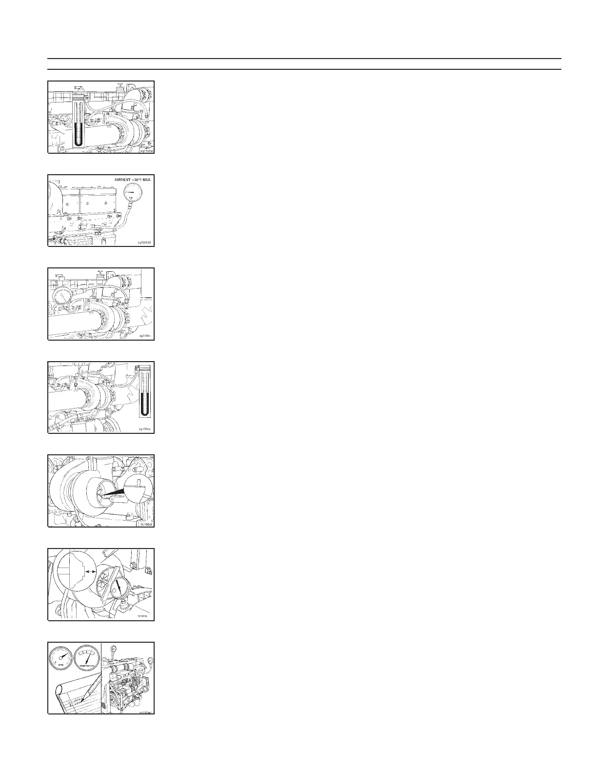
Intake Air Restriction Measured With
Water Manomometer 3-04
• Normal Duty Cleaner (Clean) 250 mm-H
2
0 MAX 10.0 in-H
2
0
• Medium Duty Cleaner (Clean) 300 mm-H
2
0 MAX 12.0 in-H
2
0
• Heavy Duty Cleaner (Clean) 380 mm-H
2
0 MAX 15.0 in-H
2
0
• Full Load Dirty Air Cleaner 635 mm-H
2
0 MAX 25.0 in-H
2
0
Intake Air Temperature 8-03
Rise Between Ambient Air and Intake
Manifold Inlet
• 310 to 410 HP 21°C MAX 38°F
• 430 to 460 HP 24°C MAX 43°F
Intake Air Temperature Rise Between
Ambient Air and the Turbocharger Inlet 17°C MAX 30°F
Exhaust Air Restriction 3-05
• Mercury Manometer (Hg) 75 mm-Hg MAX 3.0 in-Hg
• Water Manometer (H
2
0) 1016 mm-Hg MAX 40.0 in-H
2
0
• PSI 10 kPa MAX 1.5 psi
Turbocharger Radial Bearing 3-07 0.21 mm MIN 0.008 in
Clearance (Side to Side) 0.68 mm MAX 0.027in
Turbocharger Axial Clearance 3-07
(End to End) 0.03 mm MIN 0.001 in
0.10 mm MAX 0.004 in
Charge Air Cooler Differential Pressure
Across Cooler 3-11 14 kPa MAX 2 psi
102mmHg MAX 4inHg
Component Specifications and Torque Values Section V - Engine Component Specifications
Page V-12 N14
Component or Assembly (Procedure) Ref.No./Steps Metric U.S.
 Loading...