Operation
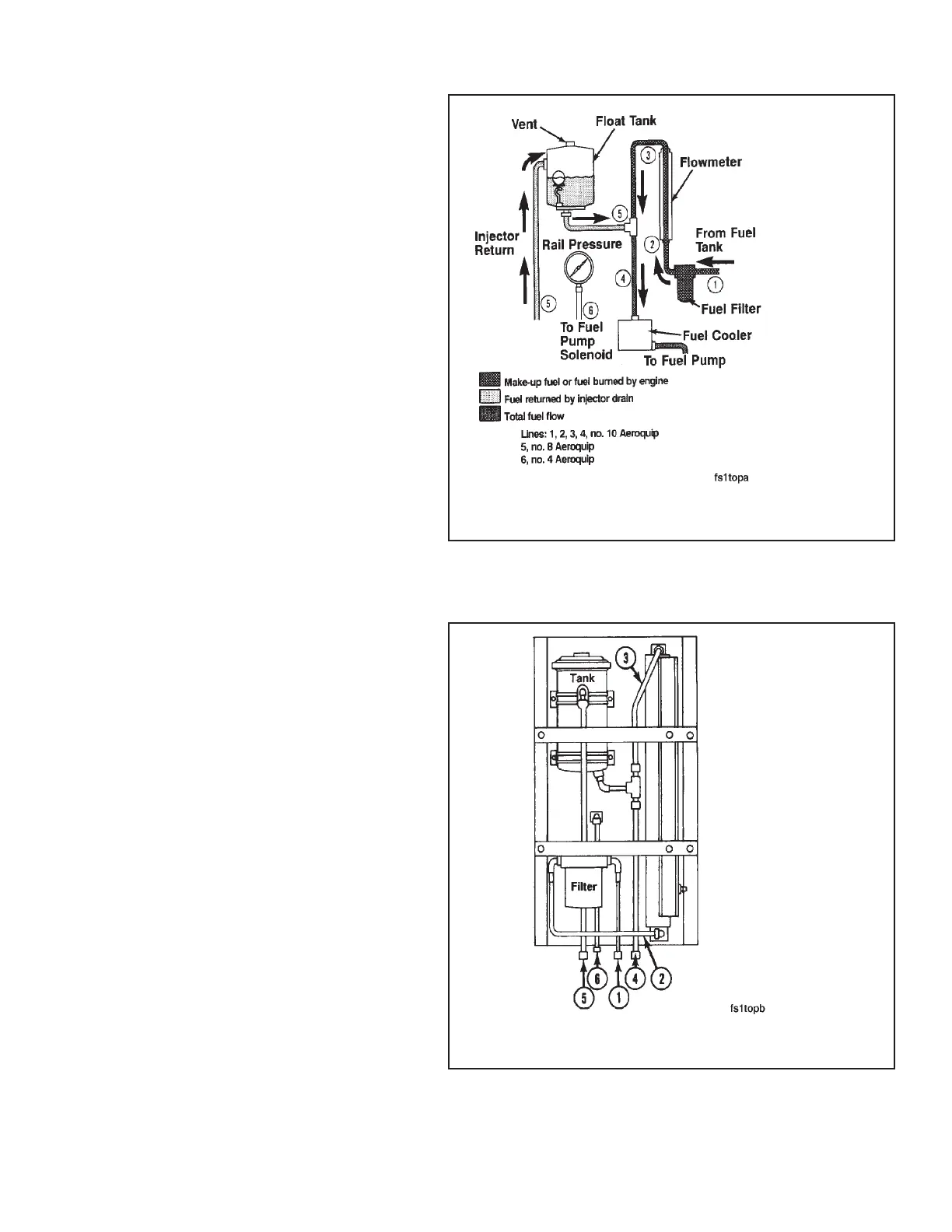
This is a schematic of the fuel measuring
device, Part No. 3376375. The device con-
sists of the following components:
• Fuel Filter
• Flowmeter
• Float Tank
• Fuel Rail Pressure Gauge
• Fuel Cooler is not a part of fuel measuring
device, Part No. 3376375; however, must
be used when conducting test with the
flow meter.
The fuel measuring device recirculates return
fuel to the engine fuel inlet by routing the
return fuel to the top side of the float tank. The
fuel is deaerated as it passes through the
baffling in the float tank. A ball float valve at
the bottom of the float tank maintains an ad-
equate volume in the tank for deaeration. The
fuel is then returned to the engine fuel inlet.
Refer to the sketch for fuel line connection
points on the fuel measuring device.
1. Fuel Supply From Tank
2. Fuel Flow to Fuel Meter
3. Fuel Flow From Fuel Meter
4. Fuel Flow to Fuel Cooler
5. Injector Return Fuel
6. Fuel Rail Pressure
Note: The fuel supply tank must be below
the level of the fuel measuring device to pre-
vent overflow of the float tank. If an overhead
fuel supply tank is used, a float controlled
reservoir must be installed between the fuel
supply tank and the fuel measuring device,
and below the level of the device.
Engine Testing Fuel Flow Measurement on Engine or Chassis Dynamometer (8-02)
N14 Page 8-21