Note: On CELECT™ engines, the engine fuel
inlet line must flow through the ECM cooling
plate to ensure proper cooling of the ECM dur-
ing engine operation.
The fuel measuring device is installed in series
between the fuel supply tank and the engine
fuel inlet. The quantity of fuel being drawn
through the flowmeter is know as ‘‘make up’’
fuel or the amount of fuel being burned by the
engine.
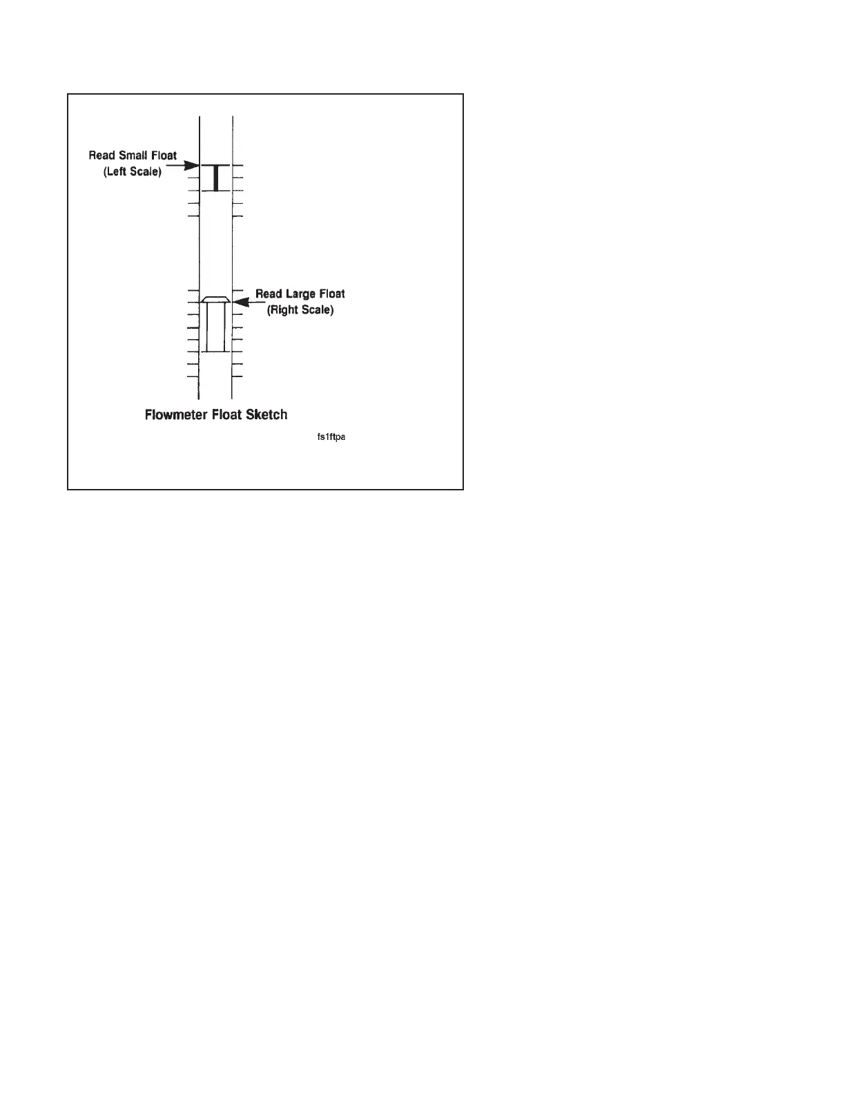
The flowmeter is graduated to read fuel flow in
pounds per hour. The flowmeter contains two
floats with respective scales on either side of
the flowmeter. The small float is used to mea-
sure lower flows and must be read on the left
scale, as shown. The larger float is for mea-
suring higher flows and must be read on the
right scale.
To obtain an accurate fuel rate measurement,
the flowmeter reading must be corrected based
on the fuel temperature. There is a fuel tem-
perature gauge on the front panel of the fuel
measuring device. The gauge is graduated in
percent of error by which the reading requires
correction. An example is: The fuel of an en-
gine reads 125 lbs/hr on the flowmeter, and the
temperature gauge reads +2 percent; the cor-
rected fuel flow rate will be 125 plus 2 percent,
or 127.5 lbs/hr.
Fuel Flow Measurement on Engine or Chassis Dynamometer (8-02) Engine Testing
N14Page 8-22