The air flow piping requires 4 inch I.D. aluminized steel
piping. The flow circuit must have as few bends as pos-
sible maximizing the length of straight sections. How-
ever, when bends are required, use long elbows. Do not
use mitered elbows, or anything that changes the air flow
direction quickly. To reduce intake air restriction, air flow
direction changes must occur gradually.
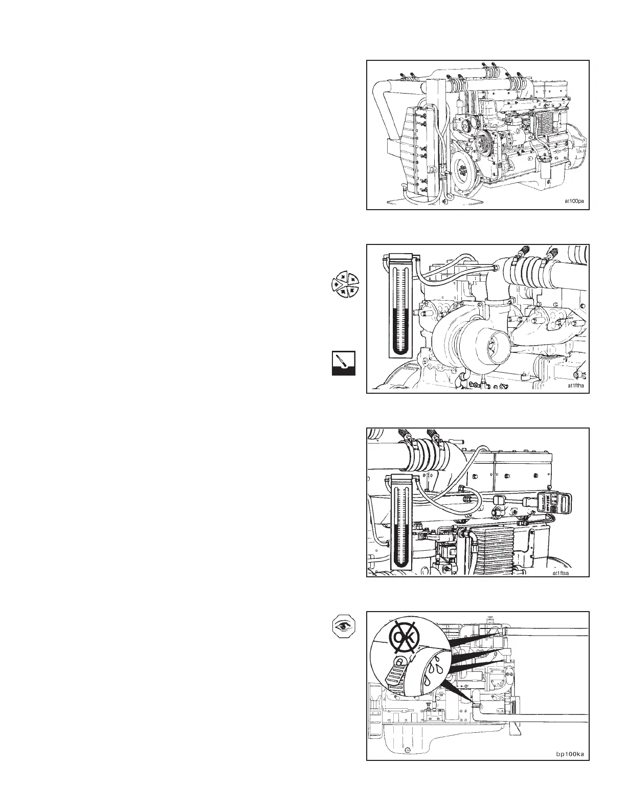
During engine test monitor the pressure drop through the
remote aftercooler. Install one end of a manometer to the
Compuchek fitting in the turbocharger compressor outlet
elbow. Install the other end of the manometer to the
Compuchek™ fitting in the intake manifold. Although less
accurate than a manometer, two individually calibrated
press (in Hg) gauges can be used to monitor pressure
drop.
The pressure drop between these two locations must not
be greater than 102 mm Hg [4 in Hg]. If the pressure drop
is greater than 102 mm [4 in Hg], check the remote
aftercoolers and air flow piping for plugging. Clean and
replace if necessary.
During engine test, also monitor intake manifold temper-
ature. Install a thermocouple (Fluke) in the 1/2 inch pipe
tap in the intake manifold. The intake air heats up as it
passes through the intake manifold so the temperature
must be measured as close to the intake manifold elbow
as possible.
If the intake manifold temperature exceeds 66°C [150°F]
during the test, make sure that there is an ample supply
of clean cool water flowing through the aftercoolers. Un-
der no circumstances must the intake air temperature be
allowed to exceed 77°C [170°F].
Visually inspect the engine for coolant leaks.
Repair all leaks found.
Engine Testing Engine Dynamometer - Install Engine (8-01)
N14 Page 8-11