15 Count value 0 to maximum count value
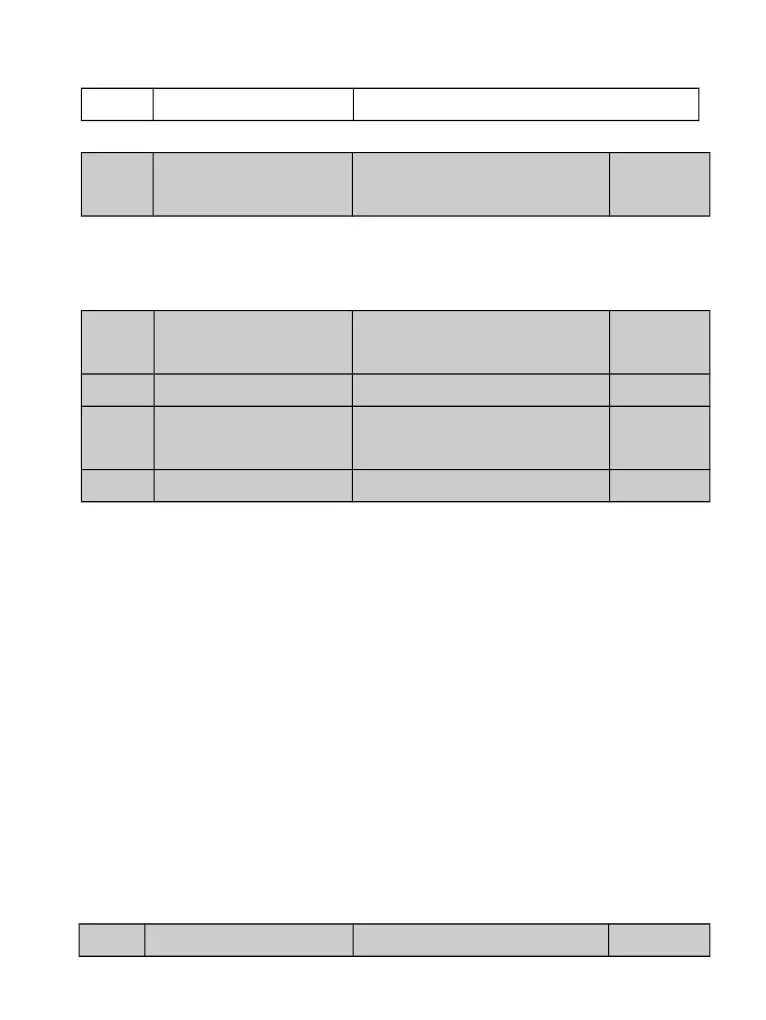
P4.09
Maximum FMP output
frequency
Setting Range : 0.01kHz~
100.00kHz
50.00kHz
If the FM terminal is used for pulse output, this parameter is used
to set the maximum frequency of pulse output.
P4.10
AO1 offset coefficient
Setting Range:-100.0%~
100.0%
0.0%
P4.11
AO1 gain
Setting Range:-10.00~+10.00 1.00
P4.12
AO2 offset coefficient
Setting Range:-100.0%~
100.0%
0.0%
P4.13
AO2 gain
Setting Range:-10.00~+10.00 1.00
These parameters are used to correct the zero drift of analog output and the output
amplitude deviation. They can also be used to define the desired AO curve.
If "b" represents zero offset, "k" represents gain, "Y" represents actual output, and "X"
represents standard output, the actual output is: Y = kX + b.
The zero offset coefficient 100% of AO1 and AO2 corresponds to 10 V (or 20 mA). The
standard output refers to the value corresponding to the analog output of 0 to 10 V (or 0 to
20 mA) with no zero offset or gain adjustment.
For example, if the analog output is used as the running
frequency, and it is expected that the output is 8 V when the
frequency is 0 and 3 V at the maximum frequency, the gain shall
be set to -0.50, and the zero offset shall be set to 80%.
P4.14
FM output delay time
Setting Range:0.0s~3600.0s 0.0s