10V +10V power Supply+10Vpower(negative
terminal: GND)
Max. output current:
50mA
GND +10V common
terminal
Grounding of analog signal
and+10V power source
Terminal COM and GND
are
Isolated inside
COM +24Vcommon
terminal
Digital signal input, output
common terminal
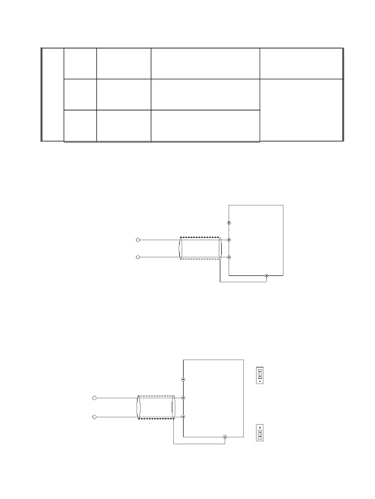
3.6.3 Analog Input/Output Terminal Wiring
(1) Analog voltage signal input through VI terminal as follow wiring:
(2) Analog signal input through CI terminal, jumper selection for input voltage (0~10V) or input
current (4~20mA) as follow wiring
+
―
—
10V
VI
GND
PE
DGI900
Shielded cable
proximal grounding
0~+10V
Fig. 3-7 VI terminal wiring
JP8
+
―
—
10V
CI
GND
PE
CI current
I
CI
V
CI voltage
DGI900
Shielded cable
proximal
grounding
0~+10V
OR 4~20mA
JP3
I
C
I
V