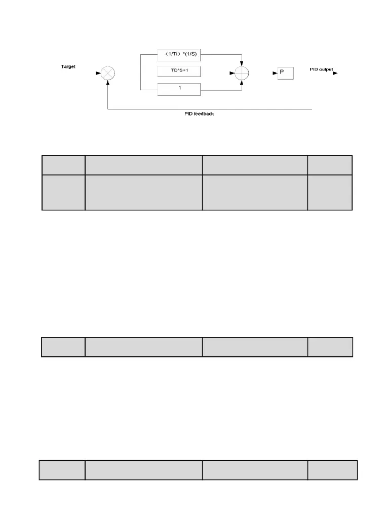
Figure 6-26 Principle block diagram of PID control
P6.00 PID setting source Setting Range : 0~5 0
P6.01 PID digital setting Setting Range:
0.0%~100.0%
50%
0:P6.01 setting;1~2: VI、CI;4:Pulse setting(X5/HDI)
5:Communication setting
P6.00 is used to select the channel of target process PID setting.
The PID setting is a relative value and ranges from 0.0% to
100.0%. The PID feedback is also a relative value. The purpose
of PID control is to make the PID setting and PID feedback equal.
P6.02 PID feedback source Setting Range : 0~8 0
0~1: VI、CI ; 3:VI-CI;4:Pulse setting(X5/HDI);5:Communication setting;6:
VI;7:MAX(|VI|, |CI |);7:MIN(|VI|, |CI |)
This parameter is used to select the feedback signal channel of
process PID. The PID feedback is a relative value and ranges
from 0.0% to 100.
P6.03 PID action direction Setting Range: 0.00s