Hardware features TransPort WR31 hardware features
Digi TransPort® Routers User Guide
46
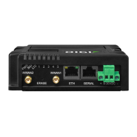
7. Serial connector: This DB9 port provides an asynchronous RS232 (RS485 optional) serial port
with optional RS422/485 support to connect the router to a compatible serial device. This is a
DCE serial port and allows CLI access to the device by default; the default serial baud rate is
115200. For a pinout, see TransPort WR31 serial pinout.
8. Power connector: A pluggable connector that connects the router to a power source using
either the separately available power supply: Digi part number 76000736, or a DIN rail power
supply.
9. WWAN primary connector: This SMA male connector connects the router’s primary cellular
antenna.
10. WWAN secondary connector: This SMA male connector connects the router’s secondary
cellular antenna. For multiple-input and multiple-output (MIMO), both cellular antennas are
needed for downloading data.
Not shown: GPS antenna connector (GPS models only): An SMA male connector that
connects the router’s GPS antenna.
11. LEDs: Indicate startup states and status for various signals and services:
n POWER LED:
Off: No power
Green: TransPort device is powered
n SERVICE LED:
Off: No WWAN network connection
Green: WWAN network connection
Flashing: WWAN traffic being transmitted or received
n WWAN LED: Indicates the presence and level of cellular service running on the device.
Off: No cellular service
1 Blink: GPRS mode
2 Blinks: EDGE mode
3 Blinks: UMTS mode
4 Blinks: HSDPA mode
5 Blinks: HSUPA mode
6 Blinks: LTE mode
n SIGNAL LEDs: Indicate strength of cellular signal.
3 LEDs: Excellent
2 LEDs: Good
1 LED: Fair
0 LEDs: Poor or No signal
n SYSTEM LED: Reserved for user-defined functions.
12. Earth ground
 Loading...