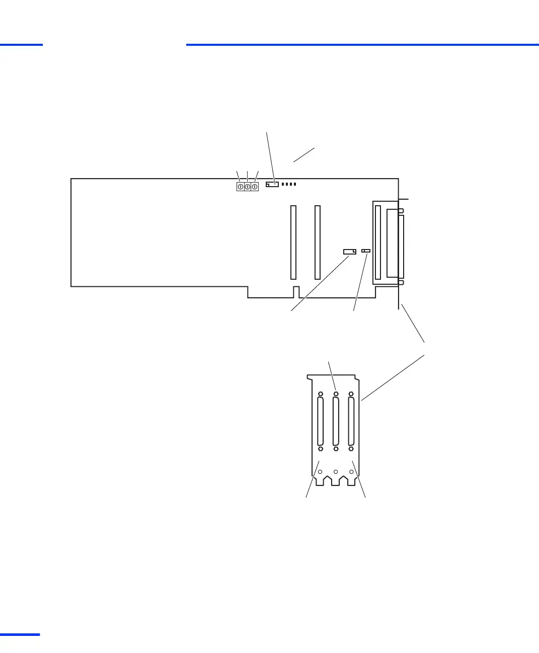
The illustration below shows the locations of the connectors, jumpers
and LEDs on the DS1103 up to board revision DS1103-07. The
illustration is not to scale.
P1P2P3
S1-1
S1-2
S1-3
1
1
1
PGVCC1
PGVCC2
RUN
BEN
JTAG programming connector (P5)
Slave DSP debug
connector (P6)
Incremental encoder/
digital connector (P3)
Slave DSP
flash jumpers (J1)
Digital connector (P2)
Analog
connector (P1)
(P3) (P2)
Status LEDs
(P1)
Bracket
s
Connector Pinouts and LEDs
t
106
s
DS1103 Hardware Installation and Configuration November 2014