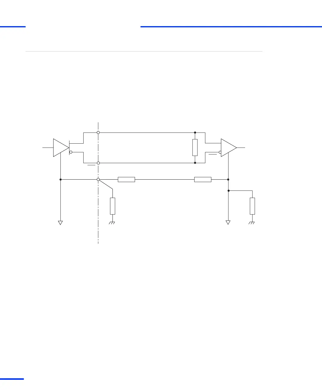
For correct operation of the transmitter and the receiver, a return
signal path between the grounding of the individual devices is
required. This can be realized by a third wire. Resistors should be
connected in series to limit unwanted high currents resulting from
ground potential differences.
The following illustration shows the grounding arrangement in an
RS422 network.
Ground connection
DS1103 (RS422 mode)
T
100 Ω
100 Ω
100 Ω
Third wire
100 Ω
Chassis
ground
Logic
ground
Chassis
ground
120 Ω
GND
Logic
ground
R
T = Transmitter
R = Receiver
RXD
RXD
TXD
TXD
s
Signal Connection to External Devices
t
192
s
DS1103 Hardware Installation and Configuration November 2014