A filter circuit at the AutoBox/Tandem-AutoBox power input can
reduce these interferences.
You do not need this filter circuit if you ensure proper
cabling and grounding of all your electronic systems in the
car.
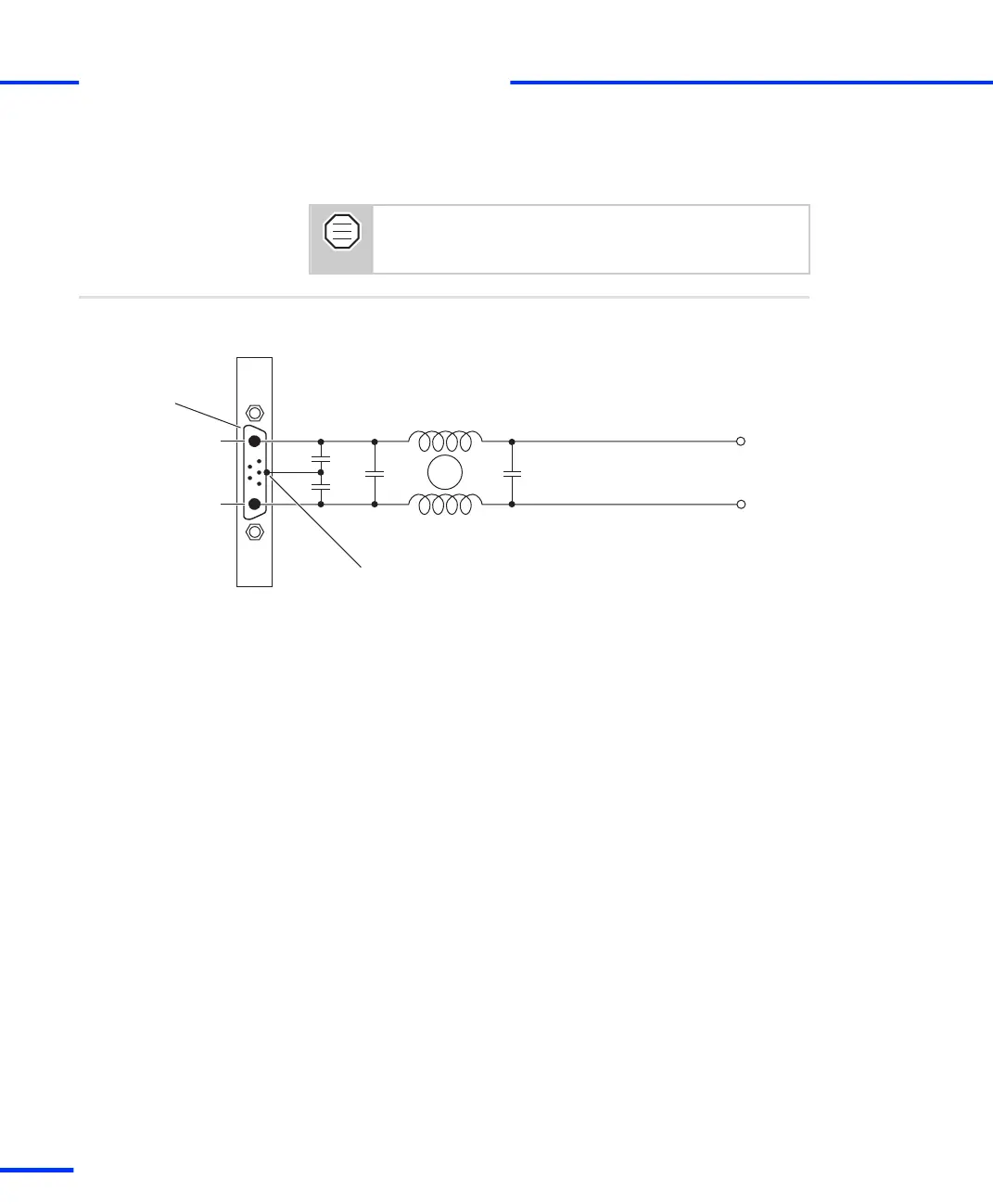
The circuit shown below only reduces conductive interferences. It is
not able to remove them.
Circuit diagram
+
–
Car battery
10 nF
1 µF1 µF
10 nF
Common-mode inductance
(approx. 50 µH)
Power input
connector
A2
A1
Connect to metal shell
The filter components must be placed close to the power input
connector of the AutoBox/Tandem-AutoBox.
The value of the common‑mode inductance is not critical. It should be
approx. 50 μH. However, the inductance must be able to handle the
max. current that can appear.
s
General Notes and Tips on Signal Conditioning
t
208
s
DS1103 Hardware Installation and Configuration November 2014