The front of the DS830 panel provides all the connectors required for
installation. The following illustration shows the front of the DS830/8.
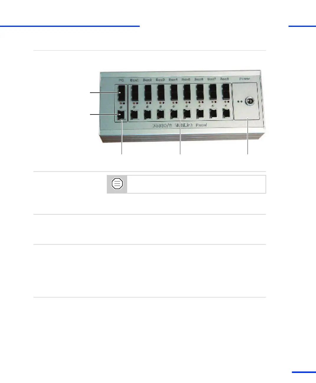
Panel front
Fiber-optic
connectors
Patch-cable
connectors
Connection to
host PC
Connection to
dSPACE boxes
Connection to
power supply
Use only the cable (fiber‑optic or patch cable) supplied with
the dSPACE hardware package.
The DS830 hardware package also includes the cables for connecting
the DS830 to the power supply.
Cables
You can supply power to the DS830 Multilink Panel:
n Via mains socket. Refer to Method 1.
n Via car battery. Refer to Method 2.
Possible methods
To connect the DS830 via mains socket
1 Connect the DS830 to the host PC.
2 Connect the DS830 to the dSPACE boxes (expansion box and/or
MicroAutoBoxes).
3 Use the cable with the integrated power supply unit. Plug the
power supply cable into the LEMO connector of the DS830.
To connect the DS830 via car battery
1 Connect the DS830 to the host PC.
2 Connect the DS830 to the dSPACE boxes (expansion box and/or
MicroAutoBoxes).
3 Use the cable with the unterminated end and connect this end to
the car battery. Use a 5 A fuse to protect the DS830.
Method 1
Method 2
s
Connecting dSPACE Boxes to the Host PC via DS830
t
DS1103 Hardware Installation and Configuration November 2014
77
t