Assembling the vacuum unit (optional)
200 Service Instructions 755 A/756 A - 00.0 - 02/2019
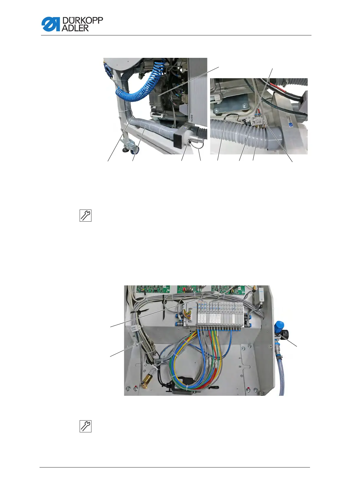
Fig. 197: Assembling the vacuum unit (2)
5. Tighten the vacuum blower (10) on the stand plate.
6. Tighten the pneumatic line (8) on the stand plate.
7. Connect the hose (4).
8. Connect cable X711 (5) of the cable harness with the pneumatic
valve (8).
9. Connect the pneumatic line (7) of the pneumatic valve (8) with the
connection (6).
Fig. 198: Assembling the vacuum unit (3)
10. Route the pneumatic line (9) through the machine head.
11. Use the Y-connection (11) to connect the pneumatic line (9) to an
existing pneumatic line that has already been connected to the
compressed air maintenance unit (12).
(4) - Hose
(5) - Cable X711
(6) - Connection
(7) - Pneumatic line
(8) - Pneumatic valve
(9) - Pneumatic line
(10) - Vacuum blower
(9) - Pneumatic line
(11) - Y-connection
(12) - Compressed air maintenance unit
 Loading...