EasyManua.ls Logo

Epson TM-H5000II series User Manual

Epson TM-H5000II series
239 pages
To Next Page IconTo Next Page
To Previous Page IconTo Previous Page
Page #230 background imageLoading...
Page #230 background image
CONFIDENTIAL
15
SHEET
App. 15
NO.
SHEET
REVISION
E
TITLE
NEXT
App. 1
6
TM-H5000
II
IIII
II
series
Specification
(STANDARD)
APPENDIX G: EXAMPLE PRINTING IN PAGE MODE
Example use of page mode is described in this appendix.
A typical procedure for transmitting commands in page mode is as follows:
Transmit
ESC L
to enter page mode.
Specify the printable area using
ESC W
.
Specify the printing direction using
ESC T
.
Transmit the print data.
Collectively print the data by sending an
FF
.
After printing, the printer automatically returns to standard mode.
Example 1: Sample program in BASIC (assumes transmission to the printer is already
possible with file #1 open)
100 PRINT #1,CHR$(&H1B);"L";
110 PRINT #1,CHR$(&H1B);"W";CHR$(0);CHR$(0);CHR$(0);CHR$(0);
120 PRINT #1,CHR$(200);CHR$(0);CHR$(144);CHR$(1);
130 PRINT #1,CHR$(&H1B);"T";CHR$(0);
140 PRINT #1,"Page mode lesson TEST 1"
150 PRINT #1,CHR$(&HC);
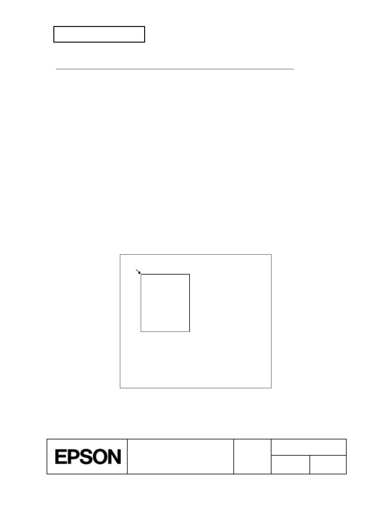
In the program for Example 1, a printable area of 200 ´ 400 dots starting at (0,0) is set, and
characters are printed on the first line of the area as shown in Figure G.1.
(0,0)
200
400
Page mode lesson
TEST 1
¬
Printable area
¬
Paper
Figure G.1 Page Mode Example 1

Table of Contents

Other manuals for Epson TM-H5000II series

Question and Answer IconNeed help?

Do you have a question about the Epson TM-H5000II series and is the answer not in the manual?

Epson TM-H5000II series Specifications

General IconGeneral
InterfaceUSB, Serial, Parallel, Ethernet
Paper Width79.5 ± 0.5 mm
BarcodeUPC-A, UPC-E, JAN13/EAN13, JAN8/EAN8, Code39, ITF, Code128, NW-7 (CODABAR)
2D SymbolsPDF417, QR Code, MaxiCode, DataMatrix
Noise Level55 dB (A) or less (during printing)

Summary

Revision History

Changed Contents Details

Summarizes modifications across revisions, detailing content updates and changes.

Confidentiality and Cautions

Usage Cautions

Lists critical warnings and precautions for safe and correct product operation.

General Printer Description

Slip Section Features

Details specific features and capabilities related to the slip printing functionality.

Receipt Section Features

Details specific features and capabilities related to the receipt printing functionality.

General Specifications

Slip Section Specifications

Covers printing specifications, character sets, and ribbon details for slip printing.

Paper Feed and Paper Specification

Specifies paper handling methods, types, and sizes.

MICR Reader Specifications

Details MICR reader functionality and requirements.

Printer Configuration

Serial Interface Configuration

Details RS-232 serial interface specifications and settings.

Parallel Interface Configuration

Outlines IEEE 1284 parallel interface specifications and modes.

Printer Connectors

Describes physical connectors for interfaces, power, and peripherals.

Printer Functions and Commands

Command List

Provides an overview of printer commands and their classifications.

Character Code Tables

Details character mappings for various languages and sets.

Error Handling and Recovery

Explains error types and procedures for recovery.

Case Specifications

External Dimensions and Weight

Provides physical dimensions and weight for installation.

External Appearance

Illustrates the printer's physical design.

Options and Consumables

Standard Accessories

Lists included items.

Consumables

Specifies compatible paper and ribbons.

Printer Commands

Command Notation and Terms

Explains command syntax and terminology.

Control Commands

Covers fundamental commands for basic operations.

Page Mode Control Commands

Details commands for advanced page mode printing.

Appendix A: Miscellaneous Notes

Printing and Paper Feeding Notes

Guidelines for optimal printing and paper handling.

Appendix B: Paper Roll Setup

Paper Roll Replacement

Instructions for replacing paper rolls.

Appendix C: Auto Cutter Error Recovery

Auto Cutter Error Recovery Procedure

Steps to resolve auto cutter lock-up errors.

Appendix D: Paper Roll Sensor Adjustment

Near-End Sensor Location Adjustment

Procedure for adjusting the near-end sensor.

Appendix E: Transmission Status Identification

Identifying Transmission Status

Explains how to interpret printer status signals.

Appendix F: Space Page Configuration

Slip Section Space Page Configuration

Configuration details for slip page.

Appendix G: Page Mode Printing Example

Page Mode Printing Procedure

Demonstrates page mode printing with examples.

Appendix H: CODE128 Bar Code

CODE128 Bar Code Description

Explains the CODE128 bar code system.

Appendix I: Print Head Cleaning

Print Head Cleaning Procedure

Instructions for cleaning the print head thermal elements.

Appendix J: Drawer Kick-out Connector Notes

Drawer Kick-out Connector Usage Conditions

Notes on using the drawer kick-out connector.

Appendix K: TM-H5000II vs TM-H5000 Comparison

TM-H5000II vs TM-H5000 Comparison

Compares key features and specifications between models.

Related product manuals