105
ELECTRICAL AND IGNITION
REMOTE CONTROL SWITCH TESTS
6
Neutral Start Switch Test
Use an ohmmeter or a continuity light to test neu-
tral start switch operation.
IMPORTANT: All wiring must b e disco nnected
from the switch before proceeding with this test.
Disassemble the remote co ntrol and remove the
neutral start switch.
Connect on e mete r lead to each terminal o f the
switch.
• Meter must indicate continuity when the plunger
is depressed
• Meter must indicate no con tinuity when the
plunger is released.
Replace switch if results are incorrect.
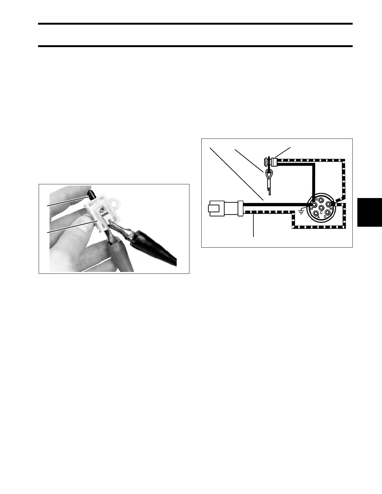
Emergency Stop Switch Test
This switc h can be part of the ke y switc h or
installed as a separate swit ch. Either st yle con-
nects the “M” terminals of the key switch.
The emergency stop switch fun ction grounds the
stop circuit wire (black/yellow) whe n th e lanya rd
clip is removed. One “M” terminal is the groun d
wire (black) and one “M” terminal is the stop circuit
wire (black/yellow).
Install th e clip on the emergency stop switch or
key switch. S tart the outb oard. Pull the clip from
the switch. The outboard must stop running.
TYPICAL
1. Plunger
2. Neutral start switch
3224
1. Lanyard and clip assembly
2. Emergency stop switch, separate from key switch
3. Stop circuit wire (black/yellow)
4. Ground wire (black)
000444