285
MIDSECTION
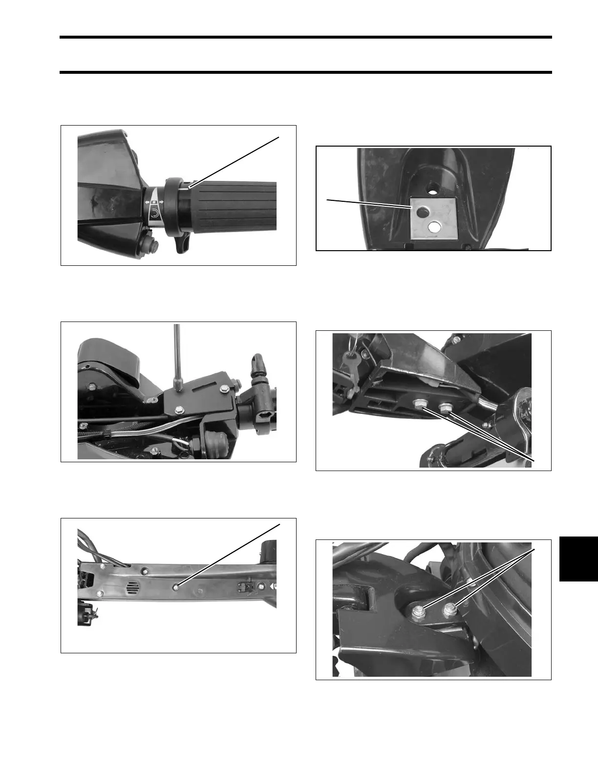
TILLER HANDLE SERVICE – LONG HANDLE
11
Be sure the twist -grip's spe ed in dicator line is
positioned with the speed range symbol on the
handle. Snap the grip into place.
Install st op switch assembly and conn ect to har-
ness.
Install b ottom cover of tiller han dle wit h seven
screws.
Installation
The ste ering arm ca n be positioned straight, or
angled 15° port or starboard by moving the adjust-
ment plate.
Place tiller bracket on steering arm from the bot-
tom. Threa d stee ring arm screws, with washers,
into steering arm and tighten to a tor que of 18 to
20 ft.lbs. (24.5 to 27 N·m).
Install locknuts on screws on top of steering arm.
Hold screws with wrench and tighten locknuts to a
torque of 18 to 20 ft.lbs. (24.5 to 27 N·m).
1. Indicator line 006719
006713
1. Cover screw 006566
1. Plate adjustment for tiller in CENTER position. 005083
1. Screw 006361
1. Screw 006362