167
OILING SYSTEM
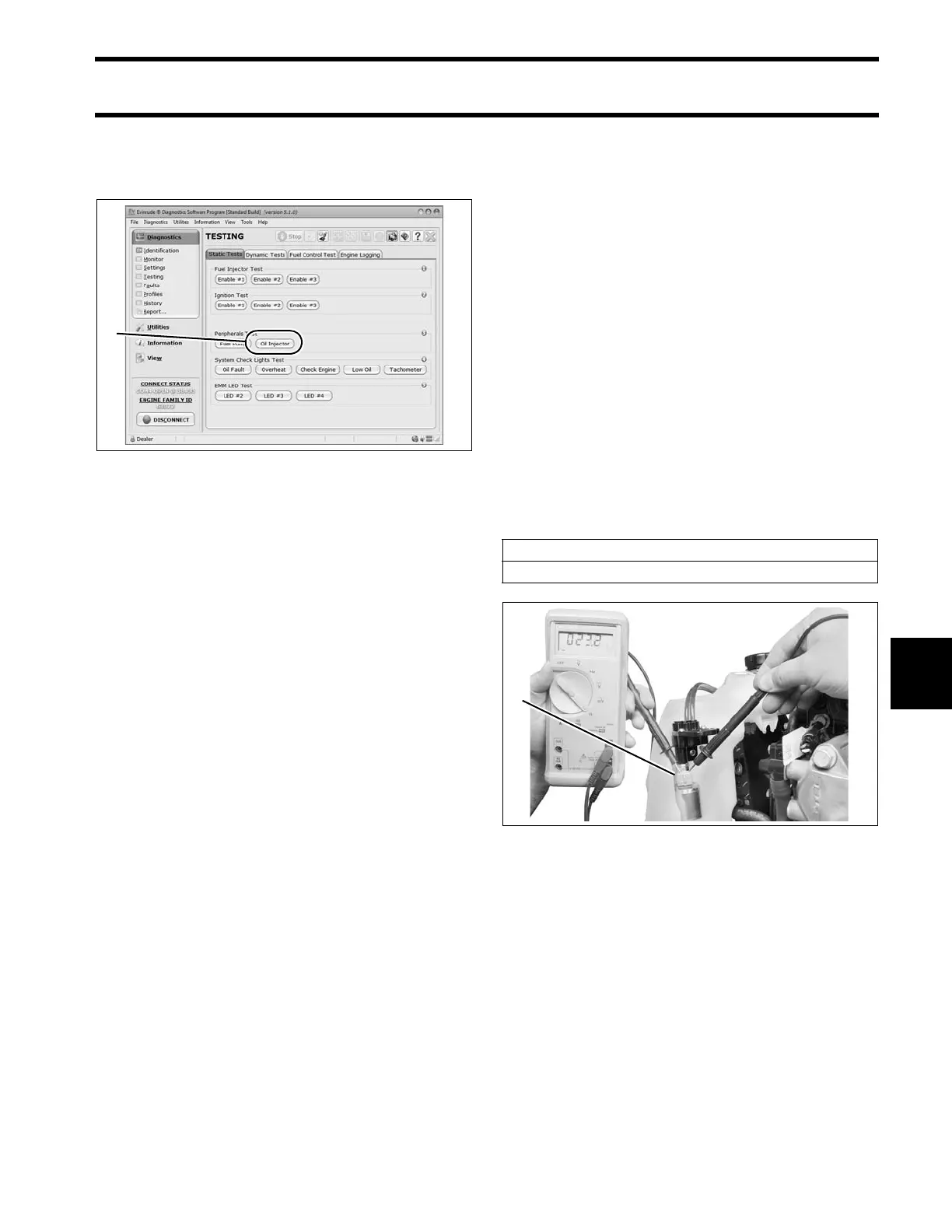
OILING SYSTEM TESTS
8
Use the Oil Injector te st o f Evinrude Diagnostic
software Static Test screen to activate the oil
pump.
IMPORTANT: This test is op erating the pump
with 12 V b attery power o n the system volt age
(55 V) circuit. The oil injection pump will not pump
oil when operating on 12 V.
Observe voltage at pin B.
• Voltage at pin B should drop as the oil pump
cycles.
Check the control signal while the Oil Injector test
is running. Set the digit al multimeter to the Hertz
(Hz) scale.
• Meter should read approximately 5 Hz.
Results:
• If volt age an d con trol signal readings at pin B
are within range, the EMM and wiring are not at
fault.
• If voltage at pin B is not within range, check volt-
age at pin A (white/red wire) of oil pump electri-
cal connector.
Connect positive meter lead to pin A (white /red
wire) of oil injection pu mp electrical connector.
Observe voltage at pin A.
• Voltage at pin A should be approximately 12 V.
Set digit al multimeter to a scale that re ads 55 V
(DC).
Start the engine. Observe voltage at pin A.
• Voltage at pin A should be approximately 55 V.
• If volt age at p in A is within range, refer to Oil
Injection Pump Resistance Test on p. 167.
• No volt age re ading at pin A, refe r to System
Voltage Test on p. 80.
Oil Injection Pump Resistance
Test
Disconnect the battery cables at the battery.
Disconnect the electrical conn ector from the oil
injection pump.
Use a digital multimeter to measure the resistance
between the pins of the oil injection pump connec-
tor. Calibrate the meter to the LOW OHMS scale.
Results:
• An infinite read ing (∞) indicates an open circuit
of th e injection pump winding. Replace faulty
pump.
Static Tests Screen
1. Oil injector test button
008082A
Oil Injection Pump Circuit Resistance
22 Ω
1. Oil injection pump connector 008420