338
GEARCASE SERVICE, 75 – 90 HP MODELS
GEARCASE ASSEMBLY
between the gauge bar and the bea ring h ousing
between each pair of scre w holes. Replace the
bearing housing and re peat check if va riance is
greater than 0.004 in. (0.101 mm).
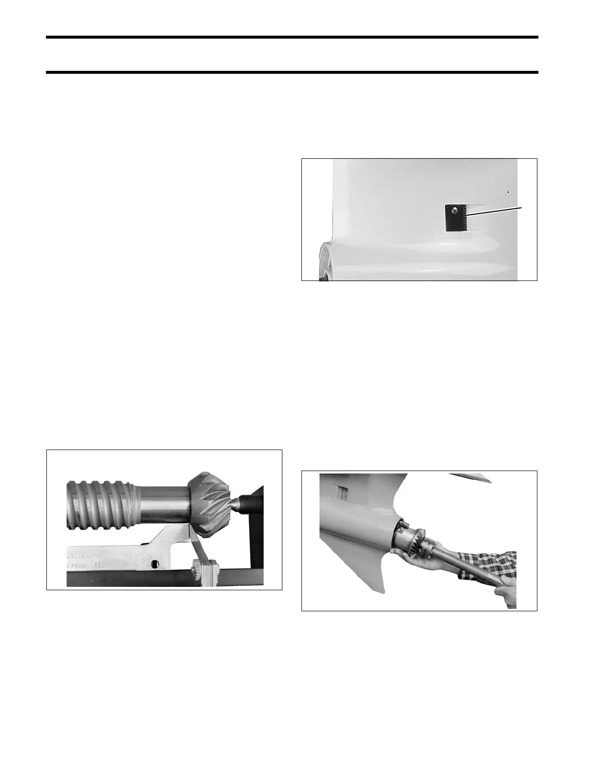
Check squareness of the pinion to the driveshaft.
Hold the shim g auge bar ag ainst the bearing
housing (between the scre w holes) while rotating
just the driveshaft and pinion assembly. Mea-
sure clea rance between the gauge bar and the
pinion at se veral locatio ns. If varia nce is gre ater
than 0.002 in . (0.050 mm) replace the pinion or
driveshaft, as necessary, and repeat check.
Subtract the averag e clearan ce measurement
from 0.020 in. (0.508 mm) to determine the cor-
rect shim thickness req uired. Sele ct t he fe west
number of shims to achieve the correct thickness.
Remove the drivesha ft from the tool and add the
required shims b etween the bearing housing and
the thrust washer.
IMPORTANT: Use extreme care when removing
bearing housing to avoid damaging the seals. Use
Driveshaft Seal Protector, P/N 318674.
Check clea rance again. The measurement
between the gau ge bar and pinion should be
0.020 in. (0.508 mm).
Remove t he nut an d pinion from the driveshaf t.
Discard the nut.
GEARCASE ASSEMBLY
Water Intake Screens
Install water int ake screens. Tighten screws to a
torque of 60 to 84 in. lbs. (7 to 9.5 N·m).
Shift Housing, Gear, and
Propeller Shaft Installation
Push sh ifter de tent into fa rthest downward posi-
tion. T ip the rea r of the gearcase slightly down-
ward to assist in th e inst allation o f th e shaf t
assembly.
Be sure the thrust bearing and the thrust washer
are in the proper position. Insert the shaft assem-
bly fully in to the gea rcase wh ile aligning shif t
housing pin wit h hole in forward e nd of gea rcase
housing.
005417
1. Water intake screen 001991
005427