275
MIDSECTION
TILLER HANDLE SERVICE – STANDARD
11
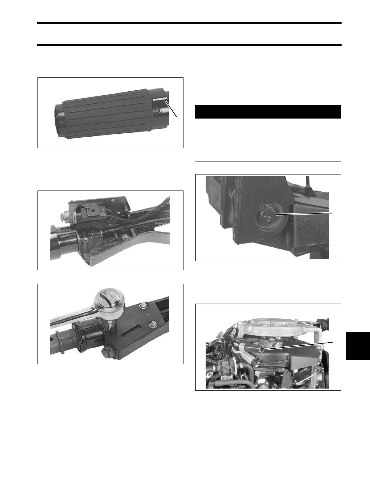
Be sure the twist -grip's spe ed in dicator line is
positioned with the speed range symbol on the
handle. Snap the grip into place.
Slide the protective sle eve ove r the stop switch
leads and throttle cable and inst all stop switch
cover.
Installation
Apply Triple-Guard grease to the two steering
handle bushin gs. Place the bushin gs into the
steering bracket. Attach the steering handle to the
bracket. Tighten screw to a torqu e of 36 t o 40 f t.
lbs. (49 to 54 N·m).
Route t hrottle cab le and electrical ha rness
through grommet in lo wer motor cover . Connect
harness to engine wiring harness.
1. Indicator line 002190
24291
24288
A CAUTION
The steering handle nut must have a nylon
patch for locking. Replace the nut if it has
lost its locking feature. Tighten the nut so
the steering handle can be pivoted and
maintained in any position.
1. Screw 31194
1. Electrical harness connector 002511