95
ELECTRICAL AND IGNITION
SENSOR TESTS
6
SENSOR TESTS
All senso r circu its a re de pendent o n wiring a nd
connections, EMM supplied current (5 V), a nd
sensor resist ance. The supplied current flows
through the wiring circuit and sensor be fore
returning to the EMM.
IMPORTANT: Use Evinrude Diagnostics sof t-
ware to monitor sensor circuit voltages or values.
Crankshaft Position Sensor (CPS)
Test
Use the Evinrude Diagnostics software CPS Sync
and engine RPM displays to confirm a valid CPS
signal while the outboa rd is cranking or running.
An RPM display higher than zero indicates a CPS
signal to the EMM.
Disconnect the crankshaft position sensor.
Use a digital multimeter to measure sensor resis-
tance betwee n the yellow a nd white wires. The
complete circuit can b e tested by measuring
between pins 6 and 7 of the EMM J1-A connector.
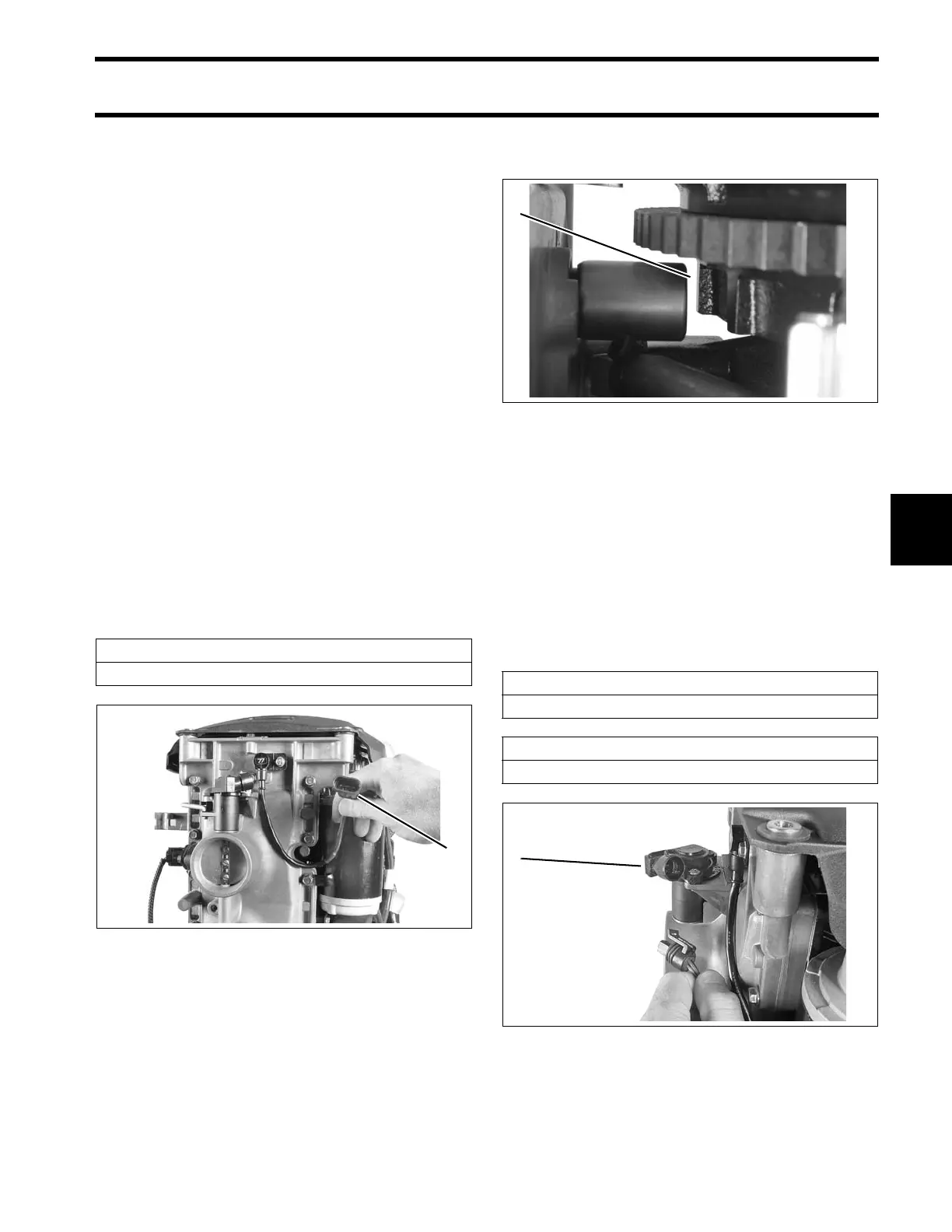
The CPS is mount ed to the throttle body housing
and requires no adjustment. Air gap or clearance
to flywheel is fixed at approximately 0.073 in.
(1.85 mm). Th e accep table clearance is 0 .036 to
0.110 in. (1 to 2.8 mm).
Throttle Position Sensor (TPS) Test
Use Evinrude Diagnostics sof tware to monitor
TPS volt age while the ou tboard is running. Volt-
age sho uld change evenly as se nsor lever is
moved.
Remove the electrical co nnector from the throttle
position sensor.
Use a digital multimeter to measure sensor re sis-
tance.
Sensor Resistance
560 Ω ± 10% @ 77°F (25°C)
1. CPS Connector 002286
1. CPS gap 006527
Sensor Resistance between “A” and “B”
3000 to 7000 Ω @ 77°F (25°C)
Sensor Resistance between “A” and “C”
4000 to 8000 Ω @ 77°F (25°C)
1. TPS 002289