106
ELECTRICAL AND IGNITION
TILT/TRIM RELAY TEST
TILT/TRIM RELAY TEST
The tilt and trim (TNT) modu le con tains the cir-
cuitry and relays required for power trim and tilt
operation.
The tilt an d trim switch provides B+ inp ut to
green/white or blue/white wire of the TNT module.
Operation
The relay activates when B+ input from the switch
is supplied to terminal 86 of the internal relays.
Terminal 87a connects to ground (B–).
Terminal 87 connects to B+.
Terminal 30 connects TNT motor.
Terminals 87a and 30 are connected when relay is
not activated. This supp lies ground (B–) connec-
tion to TNT motor.
Terminals 87 and 30 are no rmally ope n. B+ is
applied to terminal 30 when relay is act ivated.
This supplies ground B+ connection to TNT motor.
Refer to Tilt and Trim Module Diagram.
Test Procedure
Make sure r ed and black wire s are connected to
12 V battery power supply.
Set voltmeter to 12 VDC scale. Connect test leads
to terminals “A” and “B” of TNT motor connector.
Use a wire jumper to alternately connect B+ to ter-
minals “1” and “2” of tilt and trim switch connector.
The met er mu st indicate battery volt age ( 12 V)
with B+ connected to either terminal.
EXHAUST WATER VALVE
TEST
Disconnect electrical connector from wate r valve
solenoid. Use an ohmmeter to measure solenoid
resistance.
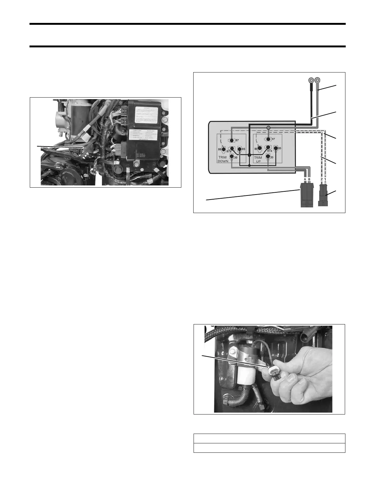
1. Tilt and trim module 006754
Tilt and Trim Module Diagram
1. Green/white wire
2. Blue/white wire
3. B+, red wire
4. B–, black wire
5. TNT motor connector
6. TNT switch connector
002063
1. Water valve electrical connector 004297
Water Valve Solenoid Resistance
295 Ω ± 20 @ 77°F (25°C)