313
GEARCASE SERVICE, 40 – 65 HP MODELS
GEARCASE ASSEMBLY
12
between the gauge b ar and t he bea ring ho using
between each pair of screw holes. Replace the
bearing housing and re peat check if va riance is
greater than 0.004 in. (0.101 mm).
Check squareness of the pinion to the driveshaft.
Hold the shim g auge bar ag ainst the bearing
housing (between the scre w holes) while rotating
just the driveshaft and pinion assembly. Mea-
sure clea rance be tween t he g auge bar and the
pinion at se veral locatio ns. If varia nce is gre ater
than 0.002 in . (0.050 mm) replace the pinion or
driveshaft, as necessary, and repeat check.
Subtract the averag e clearan ce measurement
from 0.020 in. (0.508 mm) to determine the cor-
rect shim thickness req uired. Sele ct t he fe west
number of shims to achieve the correct thickness.
Remove the drivesha ft from the tool and add the
required shims between the bearing housing and
the thrust washer.
IMPORTANT: Use extreme care when removing
bearing housing to avoid damaging the seals. Use
Driveshaft Seal Protector, P/N 312403.
Check clear ance again. The measurement
between the gau ge bar and pinion should be
0.020 in. (0.508 mm).
Remove t he nut an d pinion from the driveshaf t.
Discard the nut.
GEARCASE ASSEMBLY
Shift Housing, Gear, and
Propeller Shaft Installation
Push sh ifter det ent into fa rthest downward posi-
tion. T ip the rea r of the gearcase slightly down-
ward to assist in th e inst allation o f th e shaf t
assembly.
Be sure the thrust bearing and the thrust washer
are in the proper position. Insert the shaft assem-
bly fully in to the gea rcase wh ile aligning shif t
housing pin wit h hole in forward e nd of gea rcase
housing.
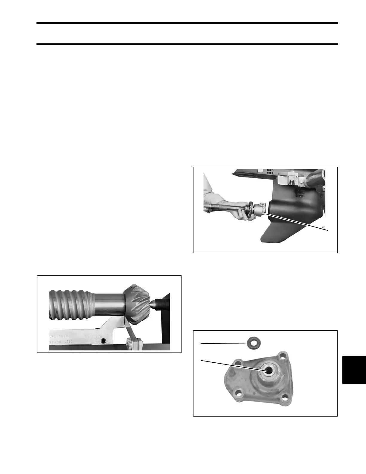
Shift Rod Housing Installation
Lubricate a new shift rod cover O-ring with Triple-
Guard grease. Install the O-ring into th e shift rod
cover.
IMPORTANT: Make sure O-ring is fully seated
in groove.
005417
1. Pin 006648
1. O-ring
2. Groove
006649