214
POWERHEAD
POWERHEAD ASSEMBLY
and tighten screw to a torque of 120 to 144 in. lbs.
(13.5 to 16 N·m).
IMPORTANT: Do not lubricate throttle levers or
shoulder screws.
Final Powerhead Assembly
Install the reed plate and throttle body assemblies.
Refer to Intake Manifold Service on p. 149.
Install oil recirculatin g hoses and che ck valves.
Refer to OIL RECIRCULATION DIAGRAMS on
p. 158, or POWERHEAD VIEWS on p. 221.
Install thermostat asse mbly. Refe r to THERMO-
STAT SERVICING on p. 182.
Install pressure valve assemb ly. Re fer to PRES-
SURE RELIEF VALVE SERVICING on p. 183.
Install shift linkage. Refer to Shift Linkage Instal-
lation on p. 212.
Install throttle linkage. Refer to Throttle Linkage
Installation on p. 213.
Install fue l injecto rs and ignition coils. Ref er to
Fuel Injector Installation on p. 147 and IGNITION
COIL SERVICING on p. 112.
IMPORTANT: All inj ectors mu st be installed i n
their original location. Improper injector installation
can result in powerhead failure.
Install st ator and flywheel. Refer to FLYWHEEL
AND STATOR SERVICING on p. 110.
Install electrical harness, then inst all EMM. Refer
to EMM SERVICING on p. 70.
Install fu el pump assemblies, fuel man ifolds, and
filter. Refer to FUEL COMPONENT SERVICING
on p. 142.
Install the oil tank and oil injection hoses. Refer to
Oil Tank Assembly on p. 169.
Install the electric st arter. Refer to S tarter Starter
Installation on p. 115.
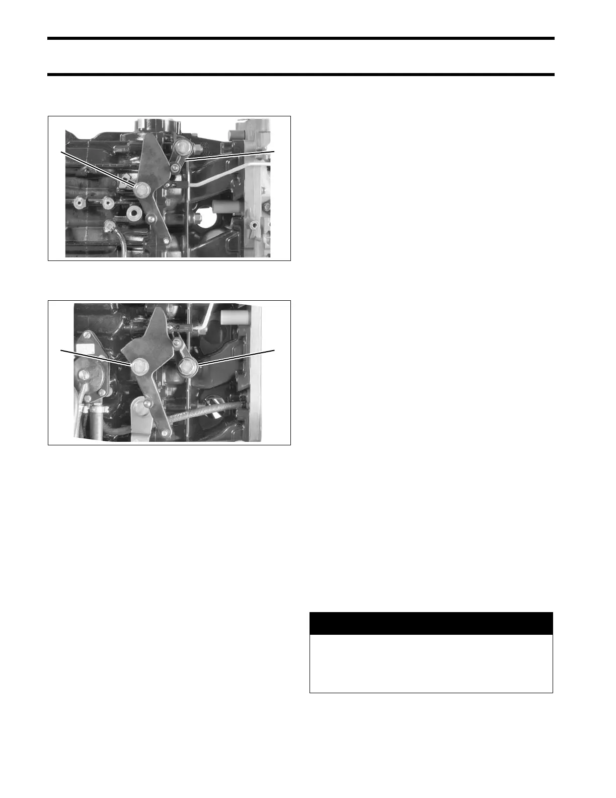
2-Cylinder models
1. Throttle lever screw
2. Throttle return lever
002245
3-Cylinder models
1. Throttle lever screw
2. Throttle return lever
002257
A WARNING
To prevent fire and explosion hazard,
make sure all electrical and ignition wiring
is routed and clamped in original posi-
tions.