79
SYSTEM ANALYSIS
IGNITION OUTPUT TESTS
5
IGNITION OUTPUT
TESTS
Use the Evinrude Diagnostics sof tware Occurred
Faults screen to check for current service code s
before troubleshooting. Correct any problems and
clear the codes FIRST.
Required Ignition Systems
Following is a comp lete list of circuits required for
ignition output:
Stop Circuit
• Black/yellow wire NOT grounded (eme rgency
stop switch lanyard in place).
Neutral Switch
• Powerhead mounted neutr al switch provides a
switched ground circuit to EMM. The circu it
enables spe cialized co ntrol fu nctions such as
neutral st art prot ection and RPM limiting in
NEUTRAL.
Stator Output Voltage
• Provides A/C voltage to EMM J2 co nnector:
Outboard cranking, typical range is 20-40 VAC
(AC output voltage is related to cranking RPM
);
Outboard running, approximately 55 VAC.
EMM
• Controls ignition grounds, injector grounds, and
engine timing.
Crankshaft Position Sensor
• Provides EMM with input.
• Outboard cranking sp eed exceeds 300 RPM
and a steady CPS signal is generated.
Alternator Output/System Voltage
• System voltage from EMM (white/red) provides
55 VDC to the high pressure fu el pump, the oil
injection pump, th e fue l injectors, and the igni-
tion coils.
Capacitor
• Connected to 55 V circuit (white/red) to stabilize
current on 55 V circuit
• Negative terminal of cap acitor mu st be
grounded.
Ignition Coil
• Primary circu its are powered by system (55 V)
voltage
• EMM provides control signal to ignition coil
• Output from ignition coil secondary winding and
high tension spark plug wire.
Wiring Inspection
Visually inspect all wi ring, con nections, and
grounds.
Use a digit al ohmmete r to test resist ance on all
ground circuits and connections. Ohmmeter read-
ings should be approximately 0.0 W.
Check that all engine wire harness g rounds have
continuity to the cylinder/crankcase.
Clean or repair all ground circuits, wiring, and con-
nections as needed.
A DANGER
The electrical system presents a serious
shock hazard. Allow outboard to sit for
two minutes after running before handling
capacitor or 55 V electrical components.
Failure to handle capacitor properly can
result in uncontrolled electrical discharge
and possible electrical shock to humans.
DO NOT handle primary or secondary igni-
tion components while outboard is run-
ning or flywheel is turning.
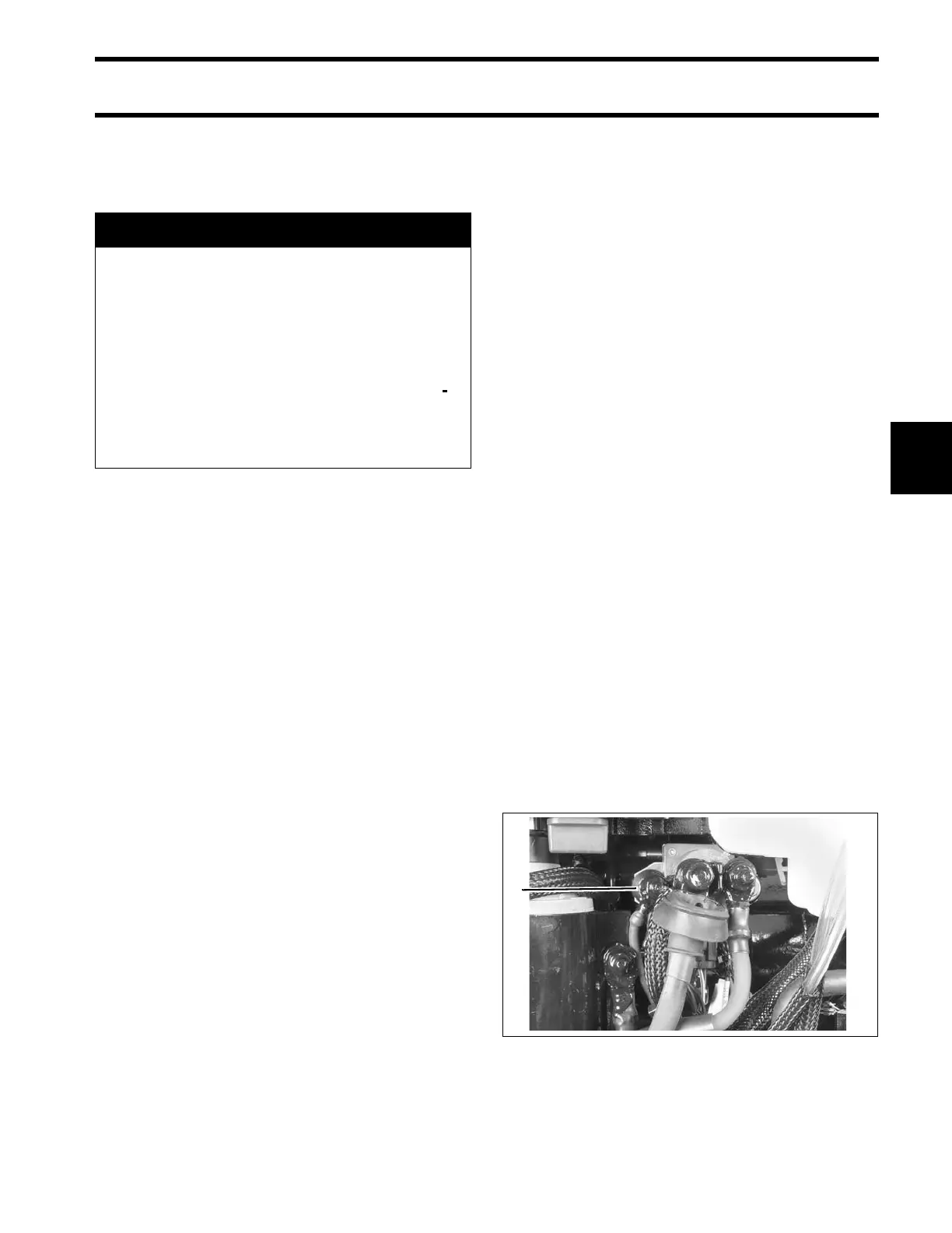
1. Main engine harness ground 002292