17
ROUTINE SERVICE
LIFTING THE OUTBOARD
2
LIFTING THE
OUTBOARD
Use correct Lifting Fixture to lift outboard:
With re coil st arter re moved, Place lif ting t ool on
flywheel and se at the three screws completely.
Refer to RECOIL STARTER REMOVAL on
p. 363.
Use only the 1 1/8 in. (short)
screws, P/N 398067, included with the tool to
avoid damage to electronic components under
the flywheel.
Fasten appropriate chain hoo k to eye of too l.
Carefully hoist outboard with chain and unbolt out-
board mounting brackets from frame.
OUTBOARD RIGGING
CONNECTIONS
IMPORTANT: For complete outboard riggin g
and remote control installation information, refer to
the Predelivery and Installation Guide included
with the service manual set.
Common Practices – All Models
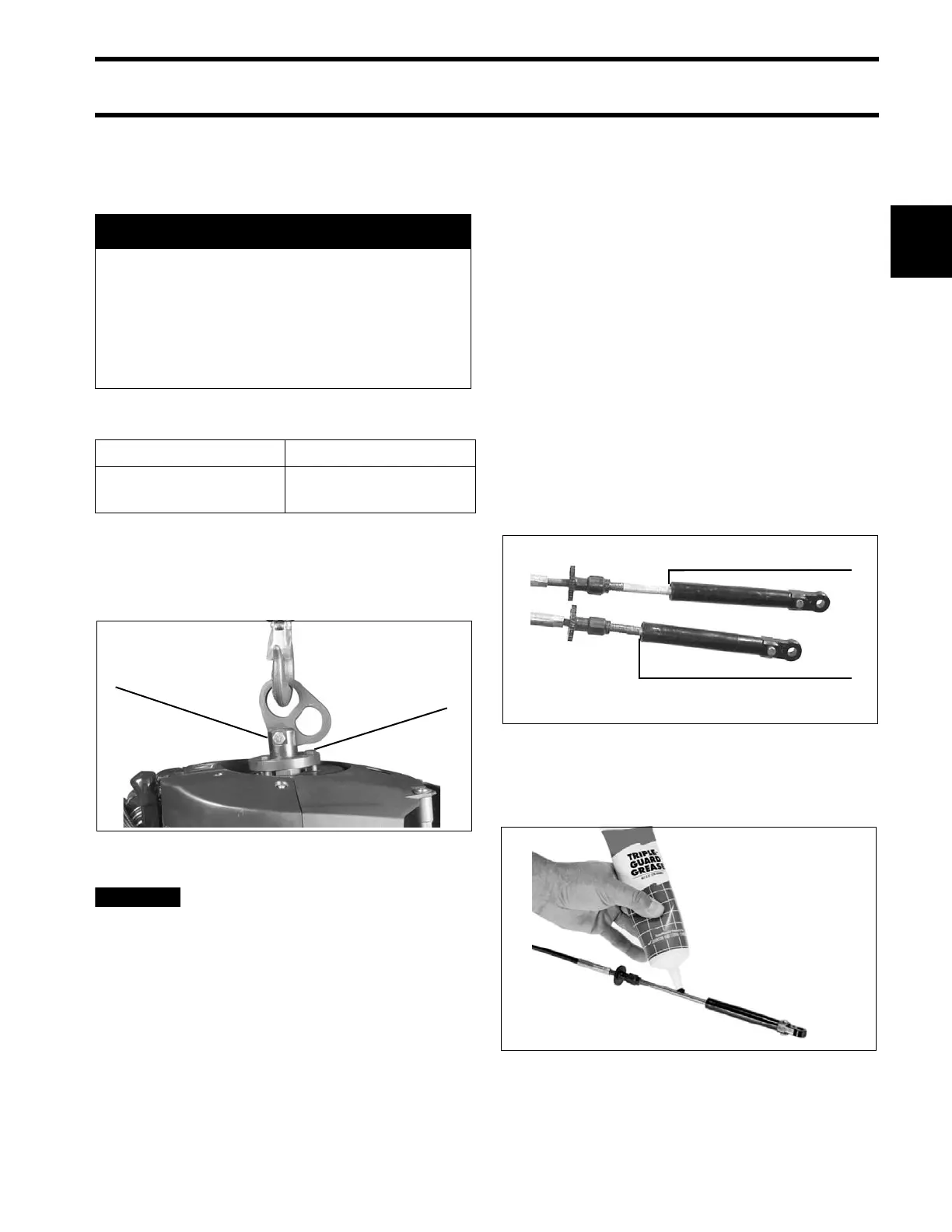
Control Cable Identification
IMPORTANT: Identify con trol ca ble fun ction
before rigging outboard.
Identify each control cable:
• Put the co ntrol handle into NEUTRAL positio n.
The throttle cable casing guide will retract com-
pletely and the shift cable casing guide will go to
the midpoint of its travel.
Extend the control cables and lubricate them with
Triple-Guard grease.
A WARNING
To avoid personal injury, make sure the lift-
ing capacity of the hoist is at least twice
the weight of the outboard.
DO NOT allow the lift hook or chain from
the hoist to come in contact with any part
of the engine during lifting.
Model Lifting Fixture
40–90 HP
P/N 396748 with
1 1/8 in. screws
1. Lifting fixture
2. 1 1/8 in. screws
002098
1. Shift cable casing guide extended to midpoint
2. Throttle cable casing guide retracted
DP0811
30501