166
OILING SYSTEM
OILING SYSTEM TESTS
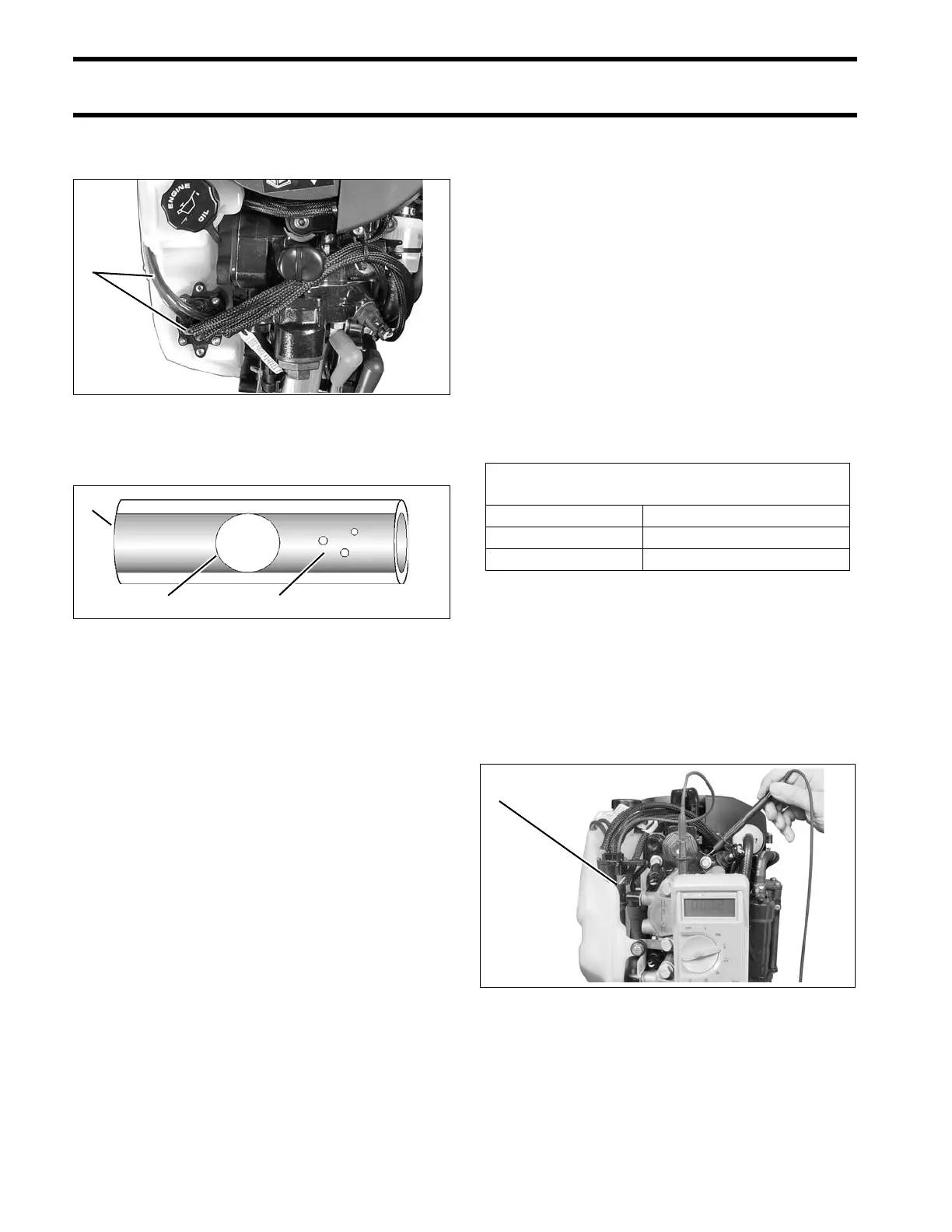
Observe oil flow through all oil distribution hoses.
Air must be purged during the priming procedure.
Small bubbles are acceptable. La rge b ubbles
must be eliminated through continued priming.
Repair any fuel or oil leaks.
The o iling system on th ese models can also be
primed using the Self-Winterizing feat ure if diag-
nostics software is not available . Refer to STOR-
AGE on p. 45.
OILING SYSTEM TESTS
IMPORTANT: Always perform visual inspections
to identify oiling system lea ks. Make sure th e oil
tank is filled and oil supply is not contaminated.
Oil Injection Pump Voltage Tests
IMPORTANT: Do NOT perform static tests using
Diagnostic Power Supply T ool, P/N 587005, with
internal 9 volt batteries only . This will p roduce
false results. Refer to Communication on p. 63.
The EMM controls the pump by providin g ground
through p in 2 3 (blue wire ) of th e J1-B co nnector
and pin B (blue wire) of the oil pump connector.
Use a digital multimeter calibrated to a scale th at
reads 12 V (DC) to mea sure voltage between the
oil pump electrical connector and engine ground.
Connect negative meter lead to ground.
Use an appropriate test probe to connect positive
meter le ad to pin B (b lue wire) of oil injection
pump electrical connector.
Turn th e key switch to the ON positio n. Observe
voltage at pin B.
• Voltage at pin B should be approximately 12 V.
1. Oil distribution hoses 007997
1. Oil distribution hose
2. Small bubbles
3. Large bubbles
004398
Acceptable Oil Injection Pump
Test Readings
Key switch ON approximately 12 VDC
Control signal approximately 5 Hz
Engine running approximately 55 VDC
1. Oil injection pump electrical connector 008065