134
FUEL SYSTEM
COMPONENTS
Fuel Circulation Pump
The fuel circulation pump is an electric high pres-
sure fuel pump.
Fuel Supply
The pump is mounted to the va por separator and
draws fuel from the fuel chamber. It pumps pres-
surized fuel through a fuel supply manifold con-
nected to the fuel injectors.
Electrical Circuit
The circula tion p ump is controlled by the EMM
and opera tes on the 55 V circuit. Th e outbo ard
must be cranking or running (CPS input to EMM)
for the circulation pump to be activated. The EMM
controls pu mp o peration by rapidly conn ecting
and discon necting th e pump’ s inte rnal coil to
ground.
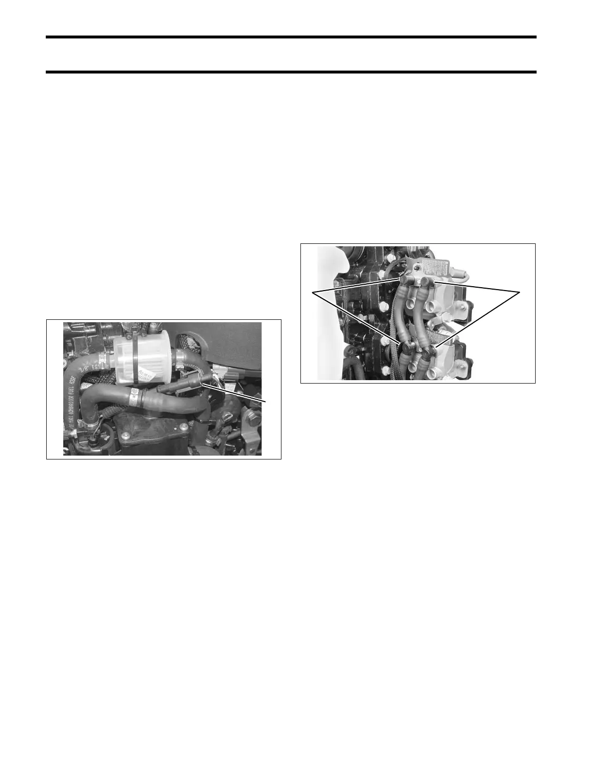
Fuel Manifolds
The fuel supply and return manifo lds route fue l
through the high pressure side of the fuel system.
Fuel Supply Manifold
The fuel supply manifold supplies pressurized fuel
to the inlet port of each fuel injector.
Fuel Return Manifold
The fuel retu rn manifold provides a route for fuel
passing through the fu el injectors t o flow ba ck to
the fuel chamber of the vapor separator.
Fuel Injectors
Fuel injectors are fuel metering, electric solenoids
(55 V) bolted directly to the cylinder head. T he
EMM controls t he activatio n of each in jector by
rapidly connecting and disconnecting the injec-
tor’s internal coil to ground.
Fuel Flow Compensation
The flow rate of each injector is measured as part
of the manufacturing pro cess. This information is
recorded and assigned to the injecto r by serial
number.
1. Fuel pump electrical connector 006557
1. Fuel supply
2. Fuel return
006560