179
COOLING SYSTEM
OPERATION
9
OPERATION
All models use a two-stage cooling system
design. The cooling system is dependent on water
pump pressure and controlled by thermost at and
pressure valve operation.
Restricted or inadequate water flow
through the outboard reduces cooling system
performance and may lead to severe power-
head damage.
Cylinder Block / Cylinder Head
Cooling
The flow of water throu gh the cylinder block and
cylinder head is controlled by a the rmostat and a
pressure relief valve. The pressure valve is
located in the top of the block next to the exhaust
cover.
The thermost at and pr essure valve co ntrol the
flow of water entering the vertical water passages
of the cylinder head.
At low speed, the pressure valve is aga inst the
seat and the thermost at is closed. W arm water
from the cylinder block gradua lly mig rates to the
thermostat pocket at the top of the cylinder head.
The thermostat opens when the water temp era-
ture reaches approximately 143°F (62°C).
When t he t hermostat opens, wat er flows down
through the cylinder head to a passage in the cyl-
inder block. W ater flows through the block to the
exhaust housing and then out of the outboard.
At higher speeds, wate r pressure op ens th e
pressure relief valve at approximately 1800 RPM.
Water flows through the valve to the cylinder head
and byp asses the th ermostat. All wa ter flo ws
through the cylinder head to the outlet passage of
the blo ck and the n exit s through the exhaust
housing.
EMM and Vapor Separator
Cooling
Cooling water is routed from the top of the cylinder
block to t he inlet fitting o f the EMM water cavity.
Cooling of the EMM helps to stabilize the temper-
atures of internal components.
IMPORTANT: Improper EMM cooling will acti-
vate service cod es 25 and 29 and the Engin e
Monitor warnin g system. Refer to the EMM Ser-
vice Code Chart at the back of this manual for
specific service code information.
Cooling water from the EMM is routed to the water
inlet fit ting of the vapor separator water cavity .
Cooling the vapor sep arator fuel chamb er mini-
mizes fuel vaporization.
Cooling water from the vapor sep arator is route d
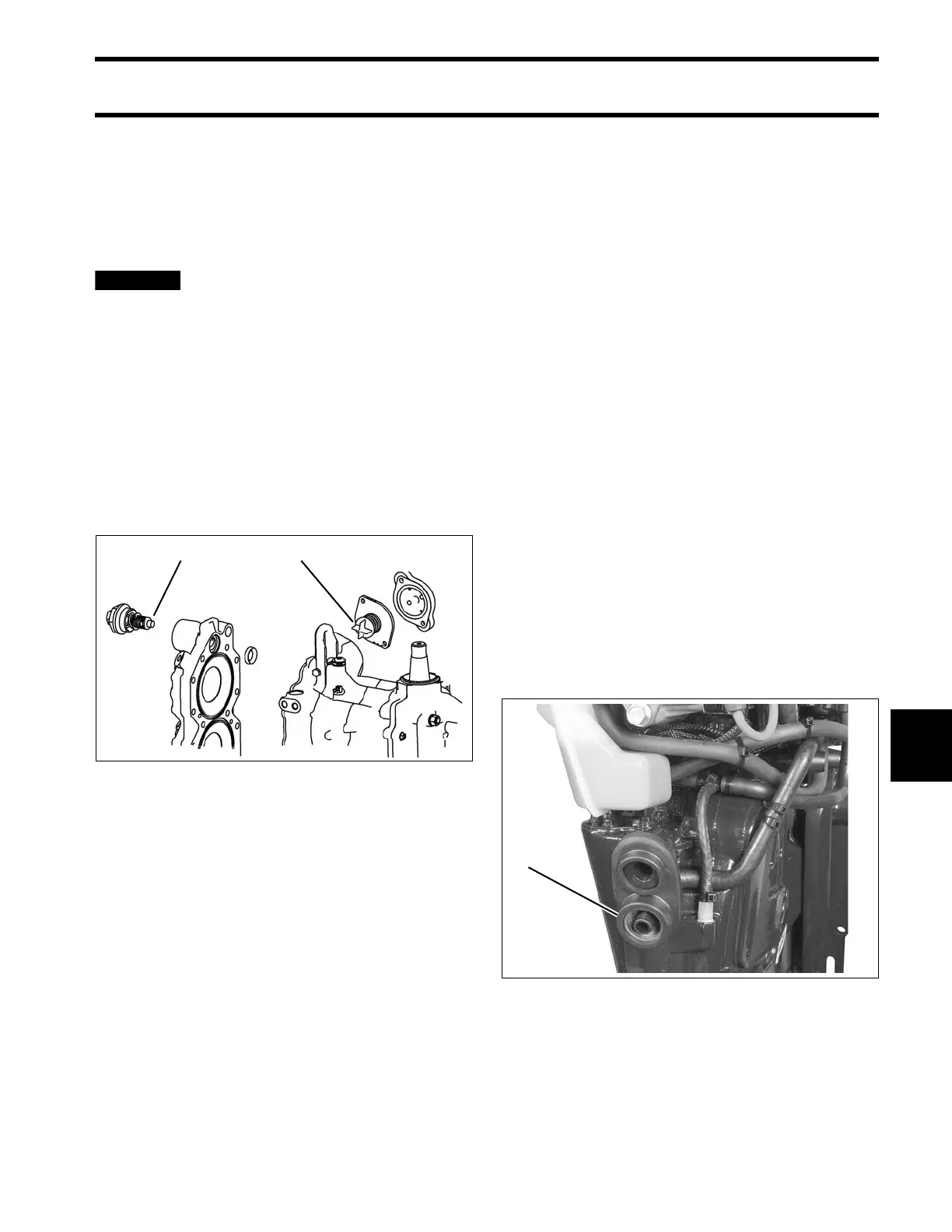
to the overboard indicator.
1. Thermostat
2. Pressure valve assembly
002441
1. Overboard indicator 004969