23
ROUTINE SERVICE
OUTBOARD RIGGING CONNECTIONS
2
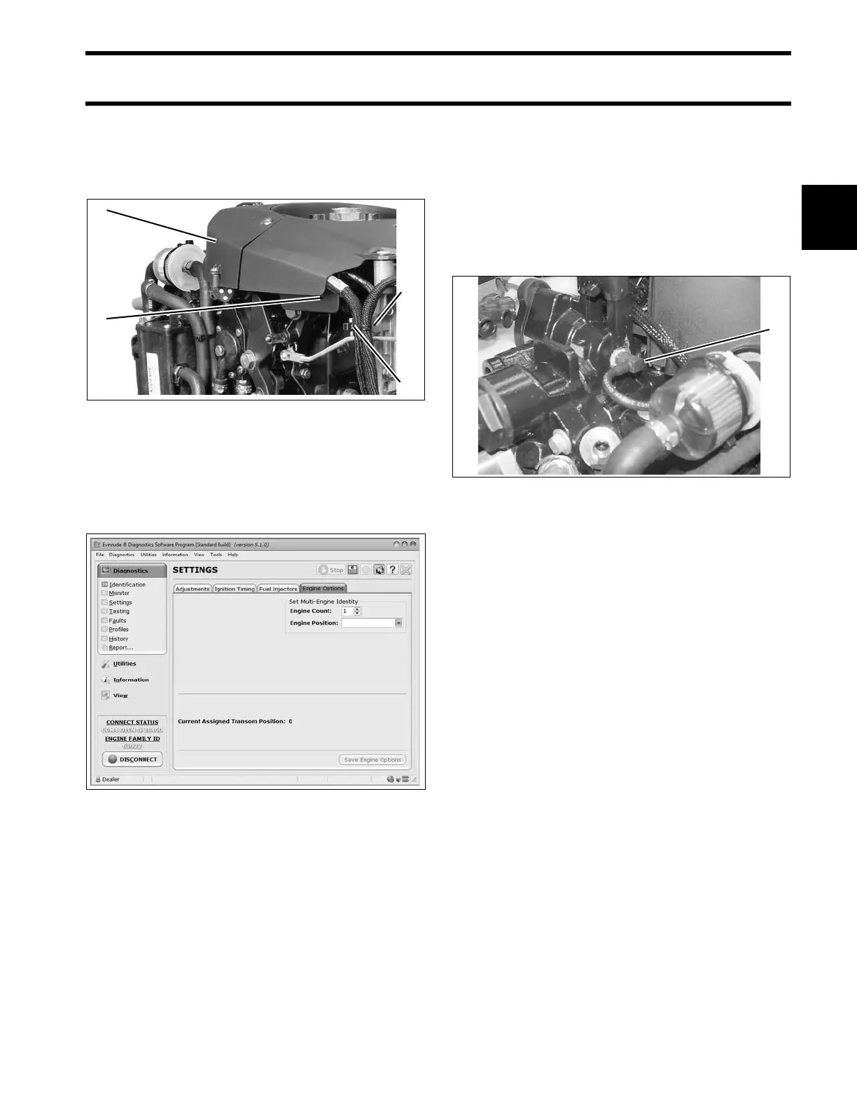
Route I-Command Ignit ion Harness throu gh wire
channel in flywheel cover . Install electrical cover.
Make sure bo th harnesses are in front o f the t ab
and tighten with tie strap.
Use Evinrude Diagnostics software to adjust net-
work settings in th e EMM. From the Settings
screen, select Engine Options.
Water Pressure Gauge
To display engine water pre ssure, install a wa ter
pressure hose fitting in th e cylind er block as
shown.
Use Pipe Sealant with Teflon on the threads of the
hose fitting. Re fer to inst allation instructions sup-
plied with gauge.
For an I-Command water pressure display , sev-
eral water p ressure senso r kit s are a vailable.
Refer to the Evinrude/Johnson Genuine Parts
and Accessories catalog.
1. Electrical cover
2. Wire channel
3. Tab
4. Tie strap
006737
Engine Options Screen 008563A
1. Water pressure hose fitting 002461