22
ROUTINE SERVICE
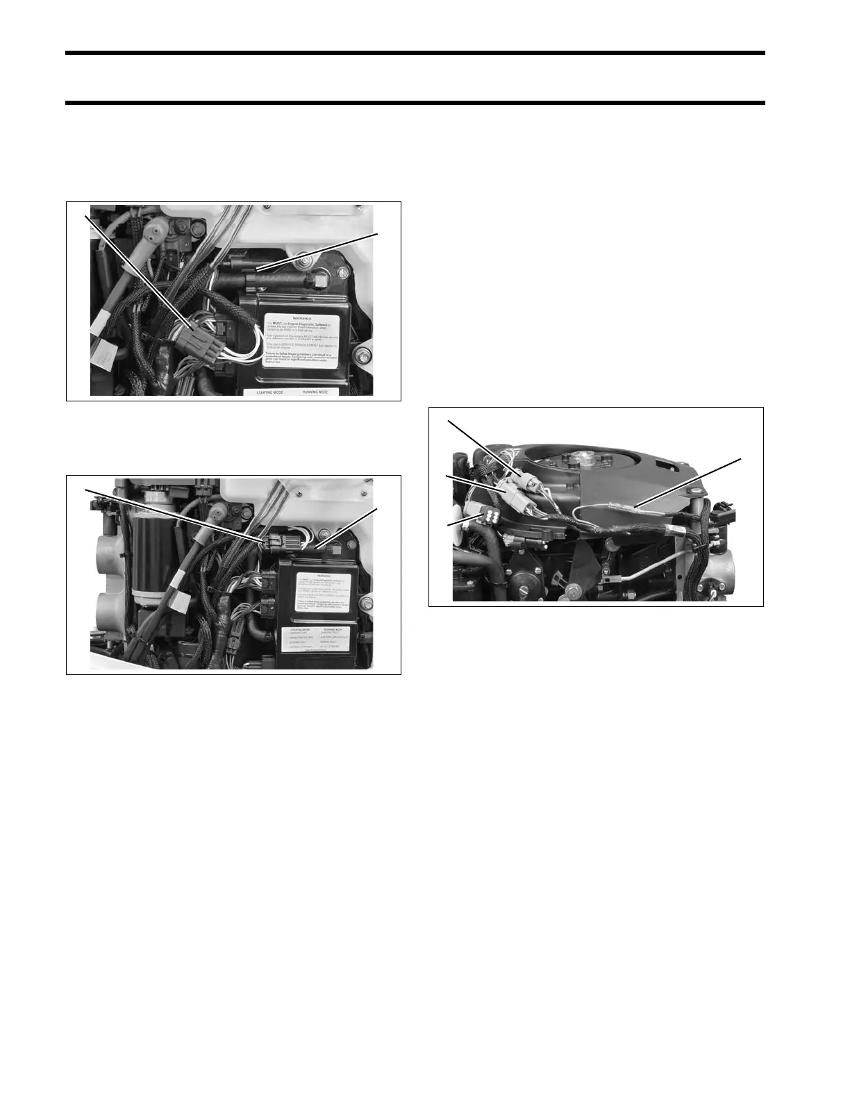
OUTBOARD RIGGING CONNECTIONS
3 CYLINDER MODELS
EMM CANbus connector cap is clipp ed to EMM
cooling water h ose. Remove clip from cap and
install on I-Command harness connector.
Install clip and connector to hose.
ALL MODELS
Adjust harness routing as needed and secure with
tie straps.
Use an I-Command Ignition and Trim Harness to
connect the outboard to the key switch and trim/tilt
control. Sea l unused SystemCheck co nnector
with 6-Pin Connector Seal, P/N 586076.
If conne cting to an existing I-Command Classic
network, connect the purple wires bet ween the I-
Command Ig nition and Trim Harn ess an d the I-
Command Engine Interface Cable. T his connec-
tion supplies power to th e network when th e key
switch is on. I-Command Digital networks do not
use this connection.
1. Canbus harness connector
2. EMM CANbus connector cap and clip
006743
1. CANbus connectors
2. EMM cooling water hose
006744
1. Trim/Tilt connector
2. CANbus Ignition connector
3. SystemCheck connector (with seal)
4. Deutsch-style harness power connector
006734