92
ELECTRICAL AND IGNITION
ELECTRICAL HARNESS CONNECTIONS
ELECTRICAL HARNESS
CONNECTIONS
Inspect wiring and electric al connectio ns. Disas-
semble a nd clean all corrode d co nnections.
Replace damaged wiring, con nectors, o r termi-
nals. Rep air any shorted electrical circuits. Refer
to wiring d iagrams and reference charts f or spe-
cific wiring details.
Refer to CONNECTOR SERVICING on p. 116.
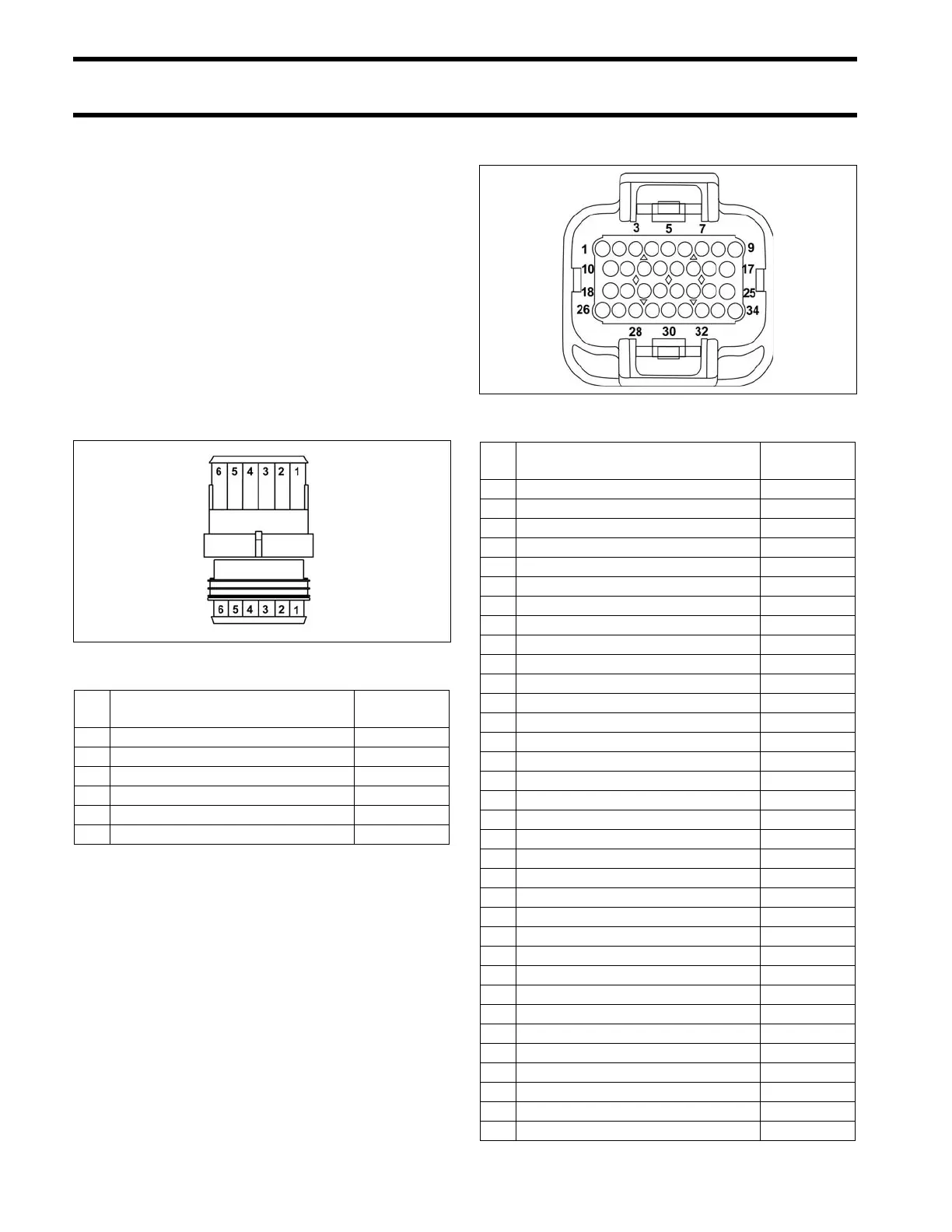
Engine Harness to Stator
Connector
EMM J1-A Connector
002025
Pin
No.
Description of Circuit Wire Color
1 Stator winding (yellow) Yellow/White
2 Stator winding (yellow) Yellow
3 Stator winding (orange) Orange/White
4 Stator winding (orange) Orange
5 Stator winding (brown) Brown/White
6 Stator winding (brown) Brown
001875
Pin
No.
Description of Circuit Wire Color
1 vacant
2 Diagnostic connector Red
3 Diagnostic connector White
4 vacant
5 vacant
6 Crankshaft position sensor (CPS) Yellow
7 Ground, CPS (digital) White
8 Bootstrap connector (programming) Blk/Orange
9 Stop circuit Blk/Yellow
10 Throttle position sensor (TPS) 5 V Red
11 vacant
12 vacant
13 CANbus, NET-L Blue
14 CANbus, NET-H White
15 12 V to EMM (fused) Red/Purple
16 Tachometer Gray
17 CHECK ENGINE signal, SystemCheck Tan/Orange
18 TPS Green
19 Engine temperature sensor Pink/Black
20 Air temperature sensor Pink/Blue
21 CANbus, NET-S Red
22 CANbus, NET-C Black
23 vacant
24 LOW OIL signal, SystemCheck Tan/Black
25 WATER TEMP signal, SystemCheck Ta n
26 TPS ground (analog) Black
27 Engine temp. sensor ground (analog) Black
28 Switched B+ to EMM Purple
29 LOW OIL switch Tan/Black
30 vacant
31 vacant
32 Neutral switch (shift linkage) Yellow/Red
33 vacant
34 vacant