220
POWERHEAD
POWERHEAD INSTALLATION
Connect the power trim connectors.
Install the lower engine covers. Re fer to LOWER
COVER SERVICE on p. 50.
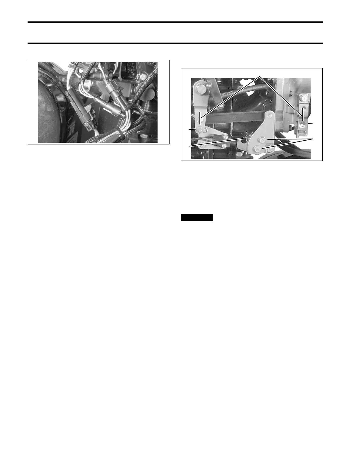
Shift Linkage Adjustment
Adjust shift linkage as follows:
• Loosen adjustment screws on shift lever.
• Be sure that ball is centered in detent assembly.
• Adjust shift lever so tha t the screw hole in shift
rod lever lines up with the hole in the gearcase
shift rod when gearcase is in neutral.
• When correctly adjust ed, the shift lever will be
parallel with th e ve rtical line of the outbo ard,
and the distance between the shift lever pin and
the cen ter of th e shif t cable trun nion pocket
should be approximately 7 in. (17.8 cm).
IMPORTANT: The shif t rod heig ht is the mo st
critical of these ad justments and should not be
moved durin g this procedure. Re fer to SHIFT
ROD ADJUSTMENT on p. 300, or SHIFT ROD
ADJUSTMENT on p. 323.
• Tighten adjustment screws to 60 to 84 in. lbs. (7
to 9.5 N·m).
Final Adjustments
After installing a new or rebuilt
powerhead, perform the following procedures
before returning outboard to service:
• Adjust timing pointer.
• Index all sp ark plugs. Refer to Spark Plu g
Indexing on p. 42.
• Use Evinrude Diagnostics software to start pow-
erhead b reak-in o iling. Ref er to Powerhead
Break-In on p. 67.
• Use Evinrude Diagnostics software to set TPS
calibration. Refer to TPS Calibration on p. 114.
• Use Evinrude Diagnostics sof tware to m ake
sure engine ma nagement software version a nd
revision are current. Update as required.
• Prime fuel system.
• Prime oiling system. Refer to Oil Supply Prim-
ing on p. 165.
• Use Evinrude Diagnostics software to check
engine timing. Ref er t o TIMING ADJUST-
MENTS on p. 113.
• Run outb oard and check for water , fu el, or oil
leaks.
• Make sure en gine rea ches correct op erating
temperature and does not overheat.
002152
1. Adjustment screws
2. Shift detent assembly
3. Shift lever pin
4. Trunnion pocket
5. 7 inch dimension
002125