253
MIDSECTION
STERN BRACKET, 75 – 90 HP POWER TILT
11
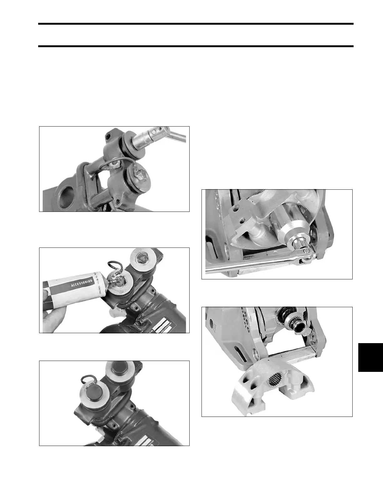
Install the tilt tu be. Tighten the tilt tube nu ts 40 to
45 ft. lbs. (54 to 61 N· m), then back of f 1/8 to 1/4
turn.
Apply Nut Lock to th reads of the upper mount to
steering arm screws. Install the mount and tighten
the screws 24 to 26 ft. lbs. (32.5 to 35 N·m). Make
sure to place the ground lead under the starboard
screw.
Apply a libera l amount of Adhesive 847 to head s
of the upper mount screws.
Place the bumpers on the upper mount screws.
STERN BRACKET,
75 – 90 HP Power Tilt
Stern Bracket Disassembly
Before servicing the stern bracket:
• Remove gearcase . Refer to GEARCASE
REMOVAL AND INSTALLATION on p. 296.
• Remove po werhead. Refer to POWERHEAD
REMOVAL on p. 190.
• Remove exh aust housing. Ref er to Exhaust
Housing Removal on p. 246.
• Remove power trim/tilt unit. Refer to TRIM AND
TILT REPLACEMENT on p. 352.
Remove and discard steering shaft locknut.
Remove the lower mount bracket and keeper.
17506
17507
17509
30738
Lower mount bracket – 20” Models 30736