170
OILING SYSTEM
OIL COMPONENT SERVICING
2-CYLINDER MODELS
ALL MODELS
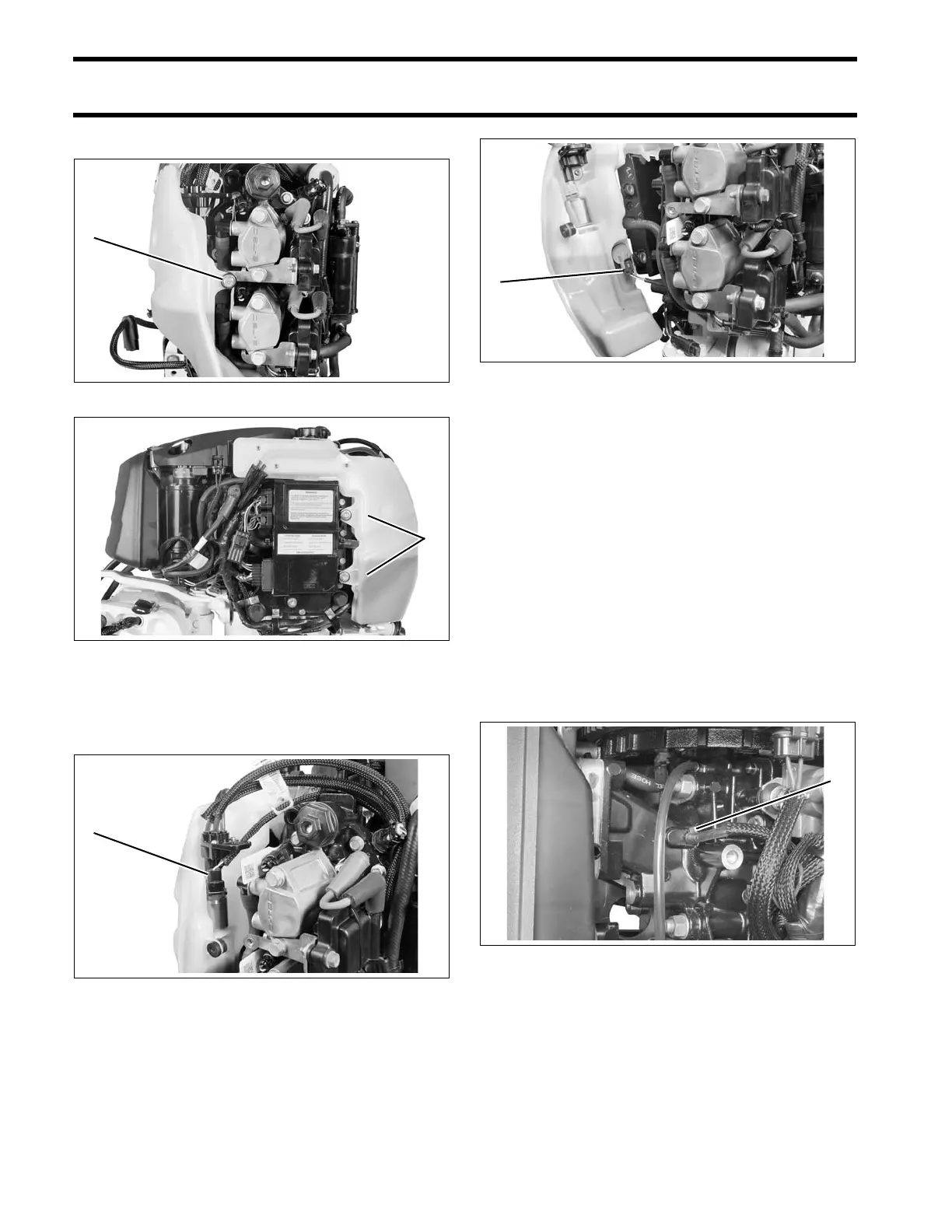
Disconnect the electrical connector to the oil injec-
tion pump and manifold assembly.
Disconnect the electrical co nnector to the lo w oil
switch.
IMPORTANT: Note oil distribut ion ho se ro ut-
ings before proceeding with disassembly.
Remove oil distribution hoses from the manifold.
Installation
Position oil t ank assembly on powerhead. Cle an
mounting screws and ap ply Nut Lock to threads.
Install screws and tighten to a torq ue of 30 to 42
in. lbs. (3.5 to 5 N·m).
Install protective sleeves and route oil distribution
hoses from the oil distribu tion ma nifold to the
crankcase oil delivery fittings. Refer to OIL SUP-
PLY DIAGRAMS on p. 156. Secure oil ho ses to
crankcase fittings with tie straps.
Run outboard and check for leaks. Use Evinrude
Diagnostics sof tware to activate “Oil Prime.”
Check oil flow through oil distrib ution hoses.
Check oil system operation and routing of oil sys-
tem hoses.
Repair an y oil leaks and kinked or misroute d
hoses. Install air silencer and engine covers.
1. Screw 008073
1. Screws 008074
1. Oil pump connector 008075
1. Low oil switch connector 008076
1. Tie strap 006573