355
TRIM AND TILT
TRIM AND TILT REPLACEMENT
13
75 – 90 HP MODELS
Install the ground lead.
Place trim/tilt unit into position. Apply Triple-Guard
grease to the lower pin and install the pin.
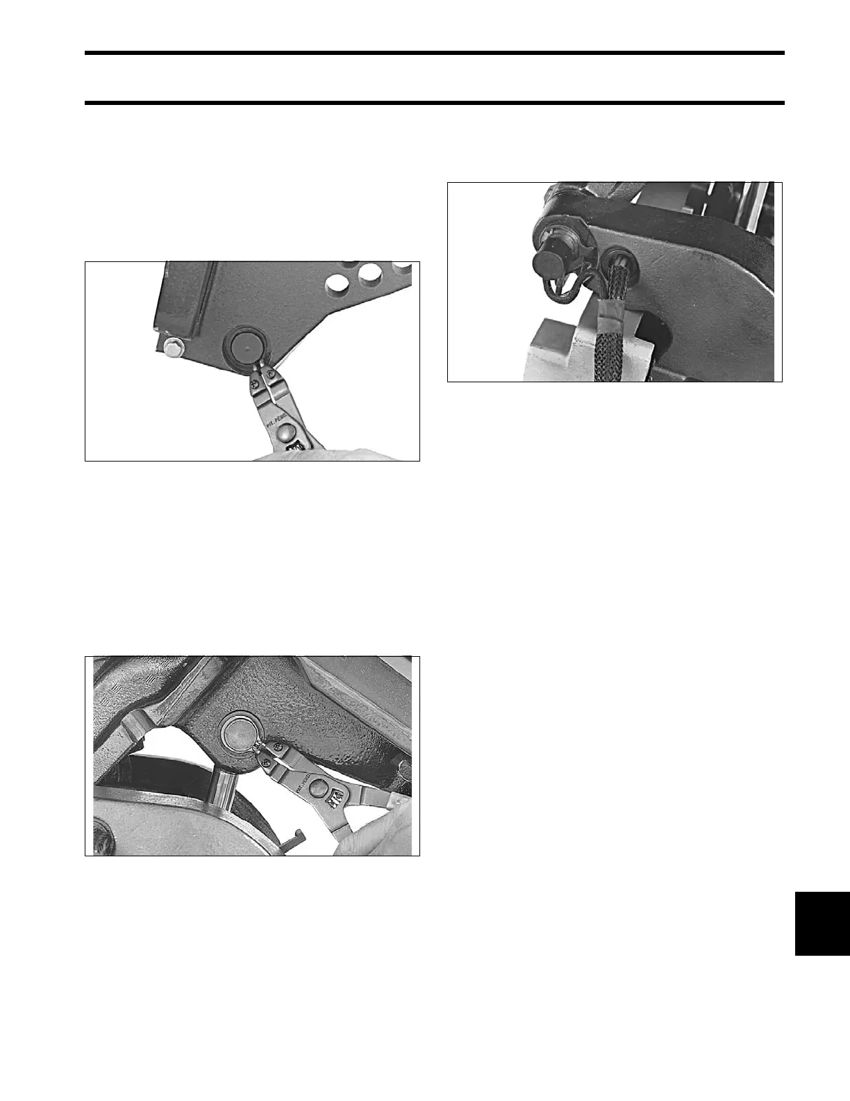
Install external snap rings on lower pin with sharp
edge of ring facing out.
Loosen the manual release valve if necessary and
extend tilt cylinder rod to match with ho les in
swivel bracket.
Apply Triple-Guard grease to upper pin and install
the pin.
Install e xternal snap rings o nto upp er pin with
sharp edge facing out.
ALL MODELS
Place trim/tilt wires in br aided tub e an d inst all
through hole in the stern bracket.
Install connector on trim/tilt cable and reconnect
trim connectors to engine wire harness.
Release t he tilt support and lower the outboard.
Tighten the manual release valve to a torque of 45
to 55 in. lbs. (5 to 6 N·m).
25077
25064
25079