System manual CECX / Analog input module CECX-A-4E-V
CECX-II 19-6
19.4.2 Analog inputs (single ended)
There are 4 analog inputs with 14-bit resolution available.
These inputs can either be used "differentially" or "single-ended".
These inputs have been designed for ratiometric measurement, and cali-
bration is standardized to U
REF
.
For further information on wiring and shielding of the analog inputs: See
System manual.
!
WARNING!
Unintentional switching on of a drive possible!
• If the power supply for the modules is not switched on, but a voltage is
applied to the analog inputs (e.g. by the external supply of an encoder),
there may still be a voltage on the analog outputs.
This enables drives to be switched on even though they have not re-
ceived an ON-command.
Remedy: The drives must only switch after the activation of an enable
output. This must only be switched on after the system startup has
been completed (e.g. via the output of a digital output module)
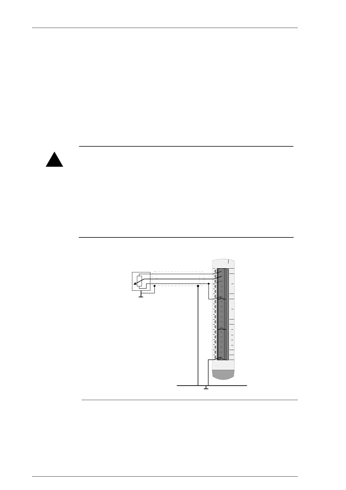
19.4.2.1 Connection example
000102030405060708091011121314151617
UREF
GND
GND
+
-
AI0
+
-
AI1
+
-
AI2
+
-
AI3
NC
NC
NC
NC
NC
GND
GND
Pxxxxx-xxxxx
shield rail
Sensor
Connection example for analog inputs (single ended)
The transducer supply U
ref
can provide a maximum of 20 mA. Number and
selection of the sensors must take account of the maximum current.

 Loading...


