System manual CECX / Analog input module CECX-A-4E-V
CECX-II 19-7
Example 1:
An analog input with a resistance sensor shall be used and shall be sup-
plied by the reference voltage:
I
ref max
= 20 mA this results in an R
min
>= 500 Ω
Example 2:
All 4 analog inputs shall be used with a resistance sensor and shall be sup-
plied by the reference voltage:
I
ref max
= 20 mA this results in an R
min
>= 4 x 500 Ω = 2 kΩ
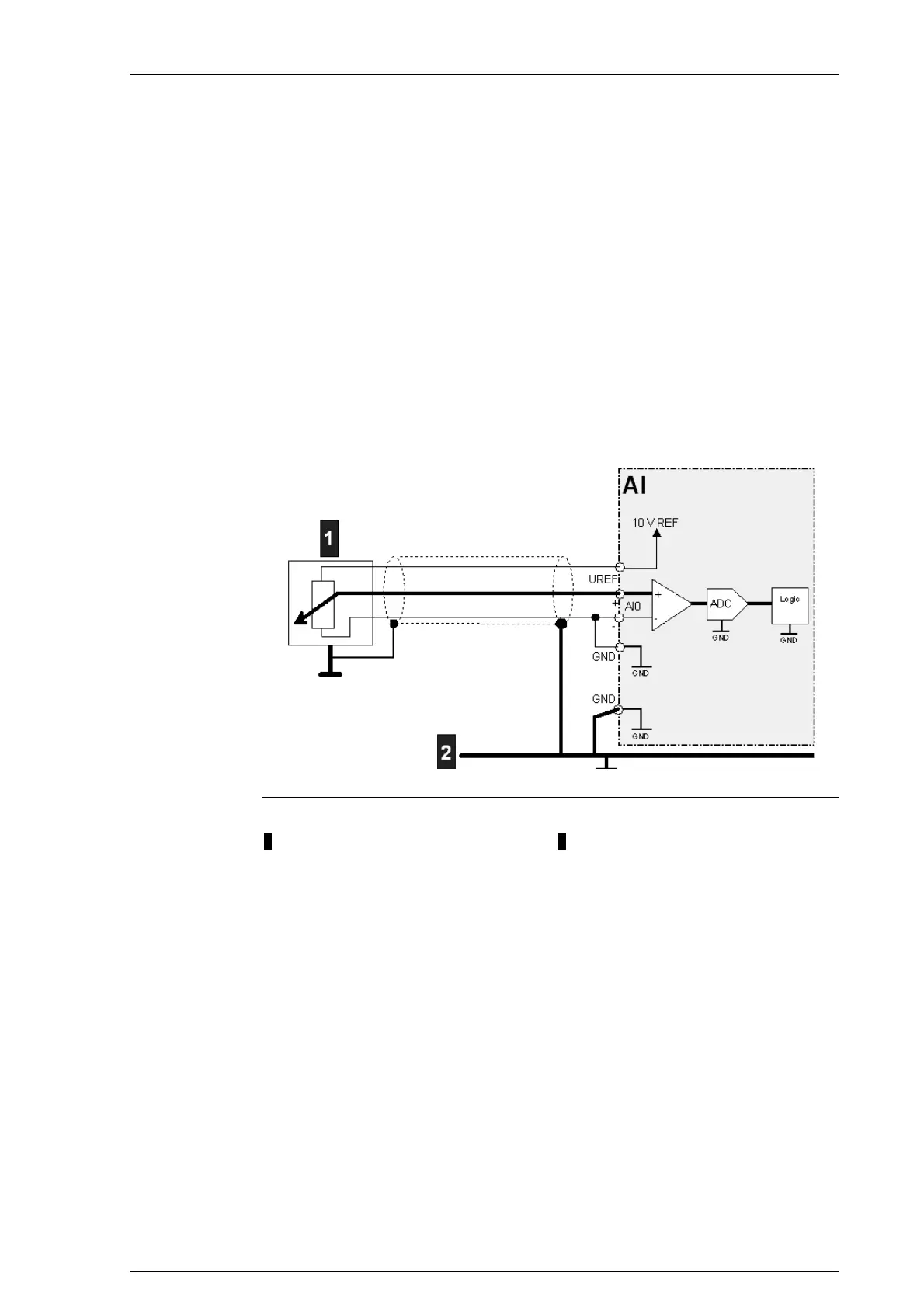
19.4.2.2 Connection diagram
Connection diagram for analog inputs (single ended)
1.... Sensor 2 Shield rail
Information on the hardware endpoints: See System manual.
19.4.3 Analog inputs (differential)
There are 4 analog inputs with 14-bit resolution available.
These inputs can either be used "differentially" or "single-ended".
For further information on wiring and shielding of the analog inputs: See
System manual.

 Loading...


