System manual CECX / Analog input/output module CECX-A-4E4A-V
CECX-II 21-7
The transducer supply U
REF
can provide a maximum of 20 mA. Number and
selection of the sensors must take account of the maximum current.
Example 1:
An analog input with a resistance sensor shall be used and shall be sup-
plied by the reference voltage:
I
ref max
= 20 mA this results in an R
min
>= 500 Ω
Example 2:
All 4 analog inputs shall be used with a resistance sensor and shall be sup-
plied by the reference voltage:
I
ref max
= 20 mA this results in an R
min
>= 4 x 500 Ω = 2 kΩ
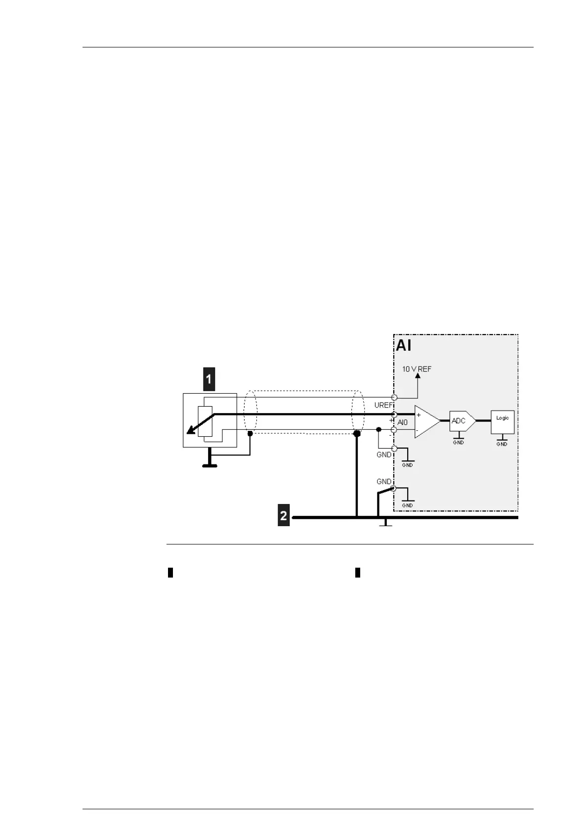
21.4.3.2 Connection diagram
Connection diagram for analog inputs (single ended)
1.... Sensor 2 Shield rail
Information on the hardware endpoints: See System manual

 Loading...


