S O F T W A R E I N S T A L L A T I O N & S E T U P C H A P T E R 6
WARNING! A 100W resistive dummy load must be connected to the amplifier output
for the Automatic Amplifier Gain Calibration procedure. Failure to do so
could cause damage to the amplifier.
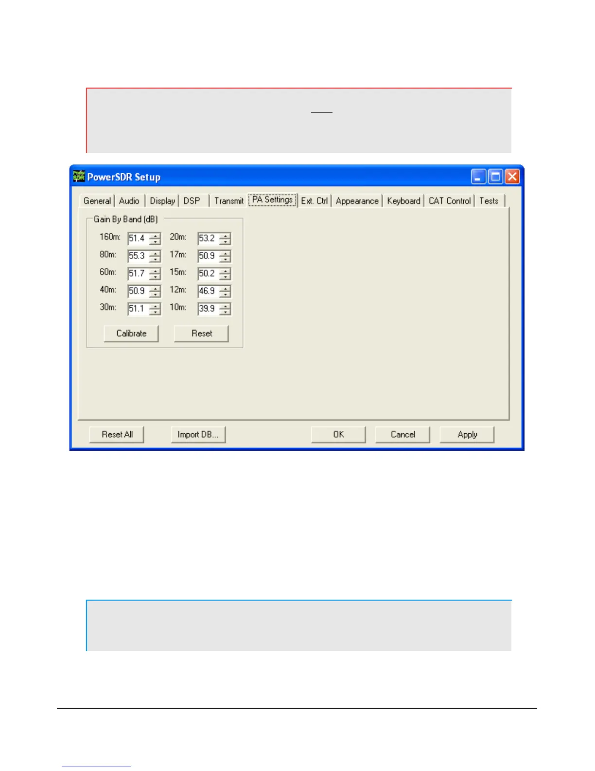
Figure 23: PA Settings Tab
Press the Calibrate button in the Gain by Band section of the PA Settings tab to start the calibration
process. Through an iterative process, the software will transmit an estimated drive for 60W (default) output
to the dummy load on each band. The power will be measured on the internal directional coupler to
determine the gain for a given drive level. The software will apply any necessary correction and save the
total system gain value for each band on the form. A progress bar will show the status of the calibration
process. An Abort button is available on the progress bar if needed to stop the calibration process. If
you get an error message during the calibration process, double check the sound card and antenna
connections and try again. Press the Apply button when finished to save the values in the database.
Note: Be sure to use the Import Database function when installing future
PowerSDR software releases in order to preserve the calibration values.
37 FlexRadio Systems
 Loading...