1 - 4
FORE Systems ES-2810 Ethernet Switch User’s Manual
Introduction to the ES-2810
1.2 Front Panel
1.2.1 Introduction
The LEDs on the front panel show the status of the ports, so you should position the switch
with the front panel facing you. You can also see which ports the cables are connected to on
the switch.
1.2.2 View of the Front Panel
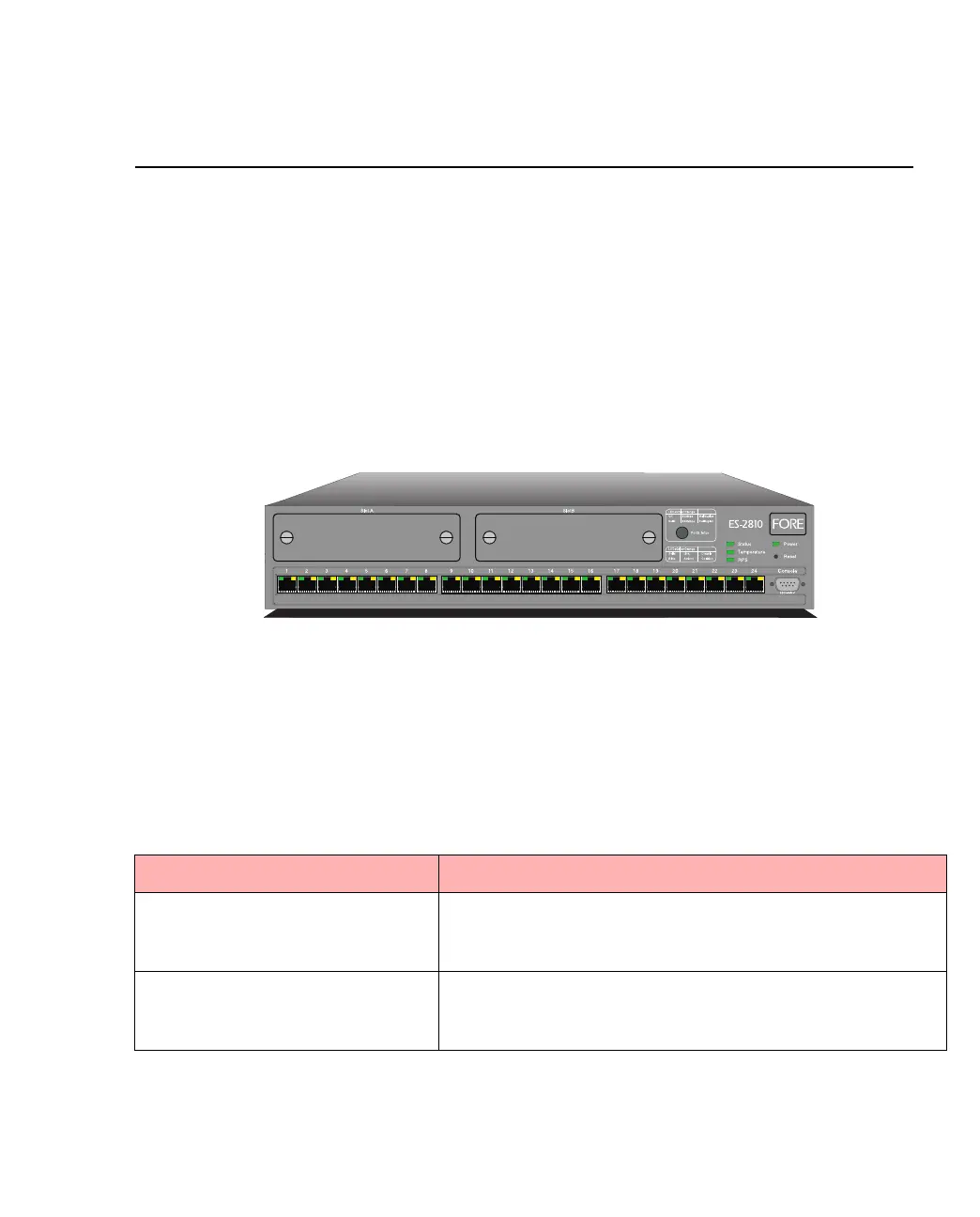
The front panel of the switch is shown below:
Figure 1.1 -
The Front Panel of the ES-2810
1.2.3 Front Panel Ports
These ports are on the front panel:
Table 1.2 -
Front Panel Ports
Port Function
CONSOLE port
(DB-9)
Connects a PC (running a VT100 emulation), a VT100 termi-
nal or a modem to access the built-in Local Management
program.
24 x 10/100Base-TX ports (RJ-45) Connects devices using Unshielded Twisted Pair (UTP)
cabling complying to EIA 568A Category 5 or ISO/IEC
11801 Category 5 level D.
1589