1 - 6
FORE Systems ES-2810 Ethernet Switch User’s Manual
Introduction to the ES-2810
1.3 Rear Panel
1.3.1 Introduction
The rear panel has a cooling fan outlet and the main supply cable, so you should position the
switch with the rear panel facing away from you.
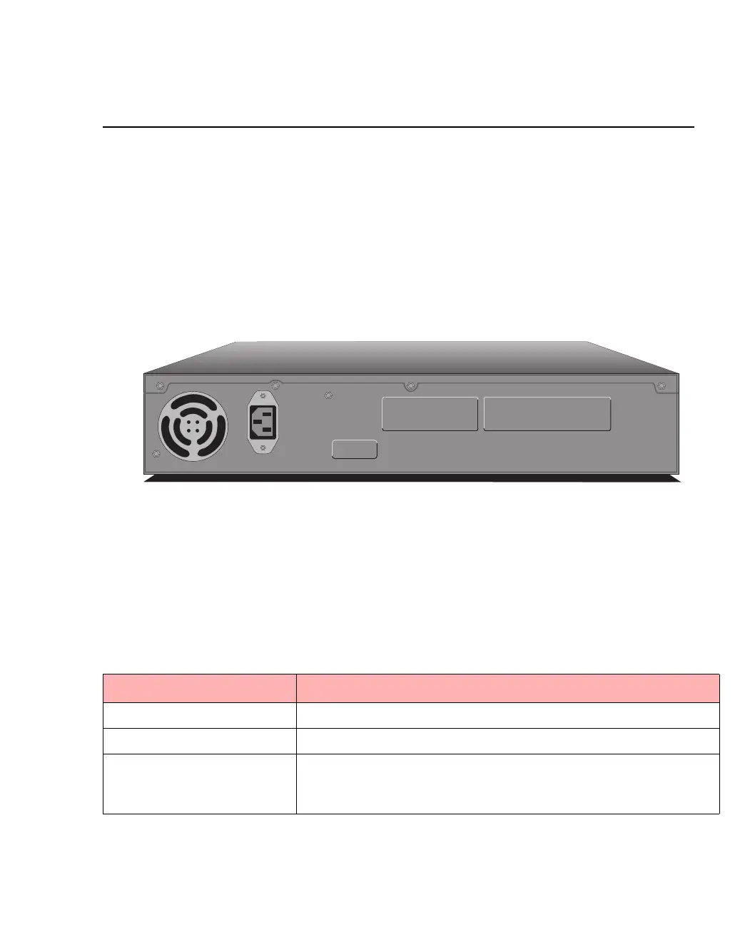
1.3.2 View of Rear Panel
The rear panel of the switch is shown below:
Figure 1.2 -
Rear Panel of the ES-2810
1.3.3 Rear Panel Parts
The switch’s rear panel has the following parts:
Table 1.5 -
Rear Panel Components
Part Function
Fan outlet Cools the internal circuitry of the switch.
Power connection A socket to connect the power cord to the main supply.
Redundant power supply
connector
Connects an external redundant power supply. If the internal
power supply fails, the redundant power supply starts immedi-
ately.
1741
Input
100-120VAC/2A
200-240VAC/1A
47Hz-63Hz
Redundant Power Supply (RPS)